This was written in old english. We did the best we could.
In this chapter I will reveal to you the way of constructing a continually moving wheel, elaborated with marvelous ingenuity, in the pursuit of which invention I have seen many people wandering about, and wearied with manifold toil. For that they did not observe that they could arrive at the mastery of this by means of the virtue, or power of this stone.
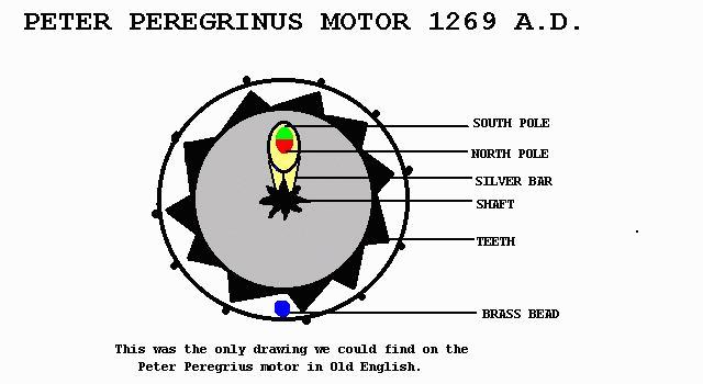
For the construction of this wheel, you shall prepare a silver case, like the case of a mirror, hollowed out, worked within with skillful workmanship, with carvings and perforations, which you shall make for the mere sake of BEAUTY, and of lightening the weight: for the lighter it shall be, the more swiftly it will move. You shall, however, make the perforations so that the EYE OF THE IGNORANT MAY NOT PERCEIVE INSIDE THE CASE, what is cunningly put therein. But inside let there be small claws or teeth of iron, of one another, so that they be not distant from one another more than the breadth of a bean or the thickness of a pea. But let the said wheel be uniform in weight of its parts. And then fix an axis through the middle, about which the wheel may revolve, the axis remaining quite immovable. To this axis also let a small silver bar be added, fixed to it, situated between the two cases, at the end of which let a magnet be set, prepared in this manner.
Let it be rounded and its poles found, as has been said. Afterward let it be fashioned in the same shape of an egg, without touching the poles, and let it be thinned down a little on two opposite sides between the poles, so that it may be flattened in shape, in order that it may occupy less room, so that it may not touch the sides of the case on the inside in the motion of the wheel. And having been so fashioned, let it be placed on the small bar, like a stone in a ring, and let the north pole be a little inclined toward the teeth of the wheel, so that the virtue may flow into the iron teeth not along a diameter, but with some inclination: so that when any tooth shall have come to the north pole, and shall be passed a little beyond the same in consequence of the impetus of the wheel, it may approach the southern part, which will repel rather than attract it, as is clear from the rule propounded above. And to each tooth will move continually in a perpetual state of attraction.
And in order that the wheel may fulfill its part the more, swiftly, shut up between the cases a little round bead of brass or silver, of such size as may be contained between any two teeth: so that when the wheel is raised, the bead will fall on the opposite side. Wherefor when the motion of the wheel is continuous toward one side, the fall of the bead also will likewise be continuous toward the opposite side being received between each pair of teeth of the wheel perpetually: and seeking by its weight, the center of the wheel or of the earth, it will prove an assistance, and will not let the teeth rest in a direct line with the stone. But let the spaces between the teeth be conveniently recessed, so that they may be able to hold the bead properly in the direction of its fall, as the present description shows.
FAREWELL......
Finished in camp, at the siege of LUCERA, in the year of our LORD 1269 on the 8th day of AUGUST endeth this treatise.
This epistle of Peter Pereginus, on the magnet written in 1269, is done into ENGLISH by Silvanus P. Thompson from the printed latin versions, Bertell 1868, and Hellmann 1898, and amended by reference to the manuscript copy in his posession, formerly amongst the Pallips Manuscripts, dated 1391, and is printed in the year 1902, in the caxton type, by Charles Whittingham & Co. at the Chiswick Press, to the number of 240 copies of which this is #27 by T.T.
P.Peregrinus -(1269 A.D.) To Lee Bowmen in 1954.
Peter Peregrinus is credited with the development of the first known and recorded permanent magnet motor in 1269.His orignal work is on file at the New York City Public Library.
The Peregrinus P.M.M. work remained dormant over the centuries until it was revived by Mr.Lee Bowman of California in 1954. Who evolved a small scale working model.
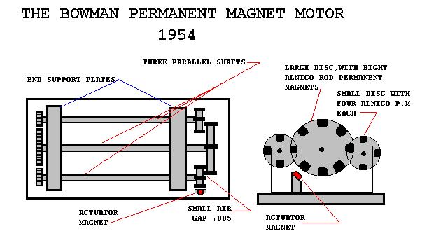
The device consisted of three parallel shafts supported in bearings within end plates secured to a solid base plate. Three gears were secured at one end of each of the three shafts, at a two-to-one ratio, with one larger gear on the central shafts, as shown.
At the opposite end, three discs were secured to the shafts ends with one larger disc on the central shaft, and the two equal size smaller discs on the two, outer shafts. The discs were also fixed at a two-to-one ratio, the same as the gear ratios at the opposite shafts ends. Eight Alnico rod permanent magnets were equally spaced on the one large disc, and four magnets each on the two smaller discs, so that they would coincide in position when the three discs were revolved. The elongated Alnico permanent magnets were placed on each of the discs so that they revolved parallel to the shafts, and their ends passed each other with a close air gap of about .005".
When the discs were moved by hand, the magnets passing each other were so phased as to be synchronized at each passing position, as shown in the sketches.
The operation of the magnetic device required the positioning of a single cylindrical permanent magnet which was placed at an angle relative to the lower quadrant of the end discs, as shown. This single magnet acted as the actuator magnet which caused the rotation of the discs by unbalancing the nagnetic forces of the three magnetic discs.
The Bowman magnetic motor was witnessed by several people including an electrical engineer who was impressed with its operation at the time of the demonstration. Although the Bowman device had received some exposure it never received any development interest and was eventually dismantled and destroyed, with no records made of its development potential.
Copyright © 1996 John Bedini
![]()