Here is a brief paper I wrote a year ago to detail a bit of my observations of this Gravity Power machine built by William F. Skinner.
This will be reposted in Energetic Forum and I’ll try to make the pictures bigger and more clear. http://www.energeticforum.com/renewable-energy/17195-william-f-skinner-1939-gravity-power.html
William F. Skinner
Gravity Power Machine, 1939
 William Frank Skinner was a prolific inventor during the early 1900’s. He was the proprietor of Skinner Manufacturing Company, Inc., in Miami, Florida.
His inventions include a toy moving picture camera, refrigerated water cooler, pulsed alkaline battery rejuvenator, amongst many other inventions.
One invention that made the national news, but apparently immediately disappeared because of its highly disruptive nature is his Gravity Power Machine.
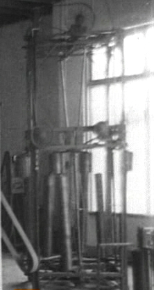
There are no patent or other documents relating to this and only old newspaper copies make any reference to it. And, an obscure video in some British archives, which you can see here: http://www.britishpathe.com/video/gravity-power/query/Skinner and video stills are available here: http://www.britishpathe.com/video/stills/gravity-power.
The basic claim is that Mr. Skinner is inputing power from a 1/8 HP electric motor and the output is claimed to be multiplied by 1200%. The output is going to a belt driven lathe and a couple other shop tools that would normally require several horsepower to operate. All that work performed for less than 100 watts.
Here is a copy of one of the nationwide newspaper articles: 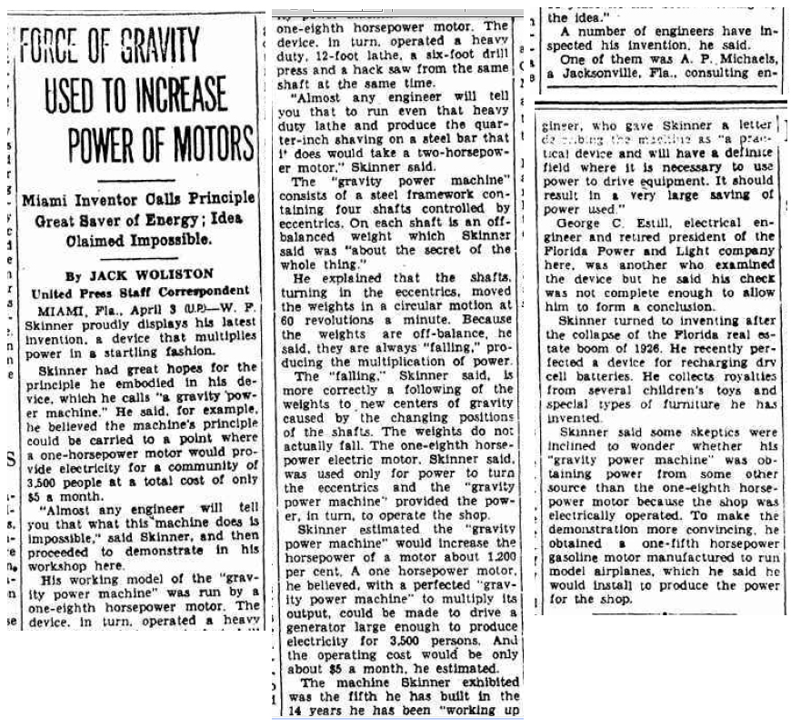
Although the claims are extraordinary, by carefully examining the machine in the video and reading the above article, we can deduce exactly what Mr. Skinner had accomplished so that we can create a replica. Let’s take a look at the main parts to the Gravity Power Machine:
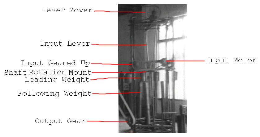
- Input is 1/8 HP electric motor.
- Geared up input wheel is belt driven from the Input Motor from a 1/8” diameter cotton thread.
- Input geared up wheel drives a belt that turns the Lever Mover, which moves the four levers back and forth.
The first three steps are simply to move the Input Levers back and forth primarily with a bit of rotation at the top of the lever. This could obviously be done in a number of ways. The back and forth is the primary motion and the slight circular motion of the level from the top increases the effectiveness of the primary mechanism.
My proposed method would be to have a Scottish Yoke assembly to convert rotational movement from a prime mover into linear back and forth movement. There are all kinds of speed controlling mechanisms available today that Mr. Skinner did not have so we should be able to greatly simplify the lever action. And of course we want a lever long enough so that the smallest input is leveraged to the max.
4. All the real action starts by the Input Lever rocking back and forth and having that movement leveraged slightly below the pivot point at the bottom.
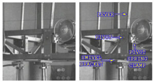
When the lever is moved back and forth, its movement pivots around the pivot point. It is not clear whether or not the lever is directly connected to the pivot or is simply clamped there by what is labeled as the “Pivot Spring Clamp.”
In the video, the lever is not solidly locked to the spring clamp as there is some “give” in both directions. It appears there is some sort of “give” mechanism such as a spring, leaf spring or other setup to possibly act as a dampener but also to assist in the leverage process. The spring clamp may be directly connected to the pivot and the lever may possibly be simply clamped in the clamp.
Although this is speculation, it does not take away from the observable fact that the bottom of the lever is moving the swivel bracket. The spring clamp doesn’t appear to be necessary for the primary operation of the machine but is there to enhance the functionality.
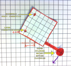
5. Looking closely at the swivel bracket, we can see that the diameter of the lever connection is smaller than the lever. So, it is possible that it is the same rod that is simply machined to a smaller diameter for practical purposes for fitting into a bearing in the bracket, or, the lever is disconnected inside of the spring clamp and a separate smaller diameter rod extends from the spring clamp down to the swivel bracket. This lower lever connection is one of three apparent connections to the bracket. The other two are a fixed connection to the upper cylinder weight, which rotates with the swivel bracket. And the other is the lower eccentric wobble shaft, which is connected to the bracket and the bracket freely rotates around this lower shaft.
We can see this clearly in the picture below:
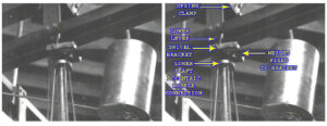
This swivel bracket is where all the real action happens.
As the cylinder weight that is fixed to the swivel bracket swings around in a clockwise direction (from a top down view), its momentum obviously has a tendency to keep it swinging in a circle. This is very important. When the lever is pushed in one direction, it is pushing one corner of the square swivel bracket and that moves in unison with the weight moving in a clockwise direction and when the momentum of the weight pulls it around towards the other direction, it helps to pull the corner that the lever is attached to in the opposite direction.
What this means is that the back and forth reaction of the lever is translated into rotational motion of the swivel bracket. And that shows us that the reaction of the back and forth helps keep the upper weight rotating in the same direction without it being opposed.
Furthermore, as the upper weight is pulled in a circle, it reinforces the lever’s input instead of counter it.
What we have here is an example of an apparent violation of Newton’s Third Law of Motion where the reaction actually assists the machine to perform in the forward direction instead of countering any movement. This is consistent with other known working mechanical amplifiers such as Veljko Milkovic’s 2-Stage Mechanical Oscillator and Fernando Sixto Ramos Solano’s Force Multiplier System where all the reaction in the system is diverted in a way so that it assists the system’s function in the forward direction.
As there is energy dissipation by the rotating upper weight, the lever only needs to input enough to make up for the loss in momentum of the weight, which is very little. Therefore, for a very small periodic input, two times per full rotational cycle, we are getting the full amount of work from the very heavy weight.
Look at the sequence of the steps with the weight rotating clockwise in relation to the pivot point from the lever that simply moves back and forth.
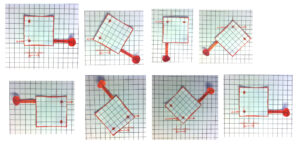
Steps 1~7 are the entire sequence and the 8th step is a repeat of the first to show the complete cycle. The below pictures shows you what each part of the swivel bracket is.
Step 1 – The lever point is to the far left and the weight is to the far right with momentum swinging it in the clockwise direction.
Step 2 – The lever point is still in the left position and the weight is still swinging around.
Step 3 – The lever point is in the same position but the weight is still swinging around.
Step 4 – At this point, the lever point is able to move towards the right direction. When pushing on the bracket from that corner in the right direction, it is in unison with the weight already moving in the clockwise direction. They reinforce each other.
Step 5 – The lever point is at the far right and the weight is at the far left.
Step 6 – The lever point is at the far right and the weight is still swinging around.
Step 7 – As soon as the bracket is situated so that the lever point can move in the opposite direction and move in unison with the weight, it moves towards the left.
Step 8 – Back to position 1.
Again, the momentum of this upper cylindrical weight carries it in a clockwise direction and this mutually reinforces the back and forth movement of the lever’s action. They are in a positive feedback cycle with each other. This translates back and forth motion to rotational movement and the rotational movement assists the lever’s back and forth movement.
As you can see, the weight is not moving around a fixed point of axis, it is moves to the left and right. It is rotating around an axis that is to the left half the time and then to the right half the time. That is the two input pulses from the lever per full rotation.
From the same sequence of steps, we can see that the point at which the lower eccentric shaft connects, it too has a none fixed orbit. Not only does the upper part of the lower shaft wobble around in a circle, it is an orbit that also has a moving axis point.
6. The next part of the trick of the system besides the Swivel Bracket mechanism is the lower weight fixed to the bottom axis of the lower shaft.
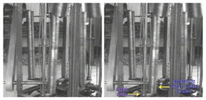
The long cylindrical weight is on a bracket that is fixed to the bottom of the lower eccentric shaft. That appears to be the only place that the lower weight is connected. It is also slightly angled outwards. With this weight, it will always try to position itself to be on the inside of the inclined shaft.
As the upper cylinder weight fixed to the Swivel Bracket rotates, the eccentric shaft is connected to the opposite corner of the bracket. The upper weight leads the bracket around and this causes the eccentric orbit of the lower shaft to constantly follow it. Therefore, since the eccentric shaft’s position is constantly changing, the lower eccentric shaft weight is constantly moving to a new center of gravity.
As long as the upper weight continues to circle, the lower weight will continue to follow.
The eccentric shaft has a fixed axis at the bottom and is connected by some means of gears, belts, etc… to a central wheel what turns the long shaft at the bottom left of the above picture. That is the output shaft and it’s power is taken from the large belt that goes to running the lathe.
To summarize, we are leveraging leverage.
We use a very small amount of energy to rock the lever back and forth. With enough length, it takes very little energy to move its connection to the bracket back and forth. The lever’s movement in conjunction with the upper cylinder weight self-reinforces each other’s movements. The back and forth movement is reinforced by the eccentric movement of the weight. And the weight’s eccentric movement is reinforced by the very small input from the back and forth movement of the lever.
As the Swivel Bracket rotates from the above stated action, the lower eccentric shaft’s connection is put on an eccentric orbit, which constantly follows the upper weight’s orbit. This causes the lower eccentric shaft’s weight to follow the upper weight producing torque at the bottom of it’s shaft that can be tapped by an output shaft.
Lever movement > moves bracket > upper weight reinforces lever’s movement > causes eccentric shaft orbit causing a moving center of gravity > lower weight constantly moves to the moving center of gravity causing mechanical shaft power at the bottom.
No laws of physics are violated. It is an open non-equilibrium thermodynamic system that is open to free gravitational potential. This gravitational potential is able to constantly act as a source of work energy on the lower weight because of the constant shifting of the center of gravity that the lower weight is seeking.
From a little input on the lever, we are able to massively amplify the amount of work we can take from the output by the described mechanism. This appears to be the highest COP (coefficient of performance) mechanical amplifier that has ever been revealed to the public.