THE YEAR IS 1984
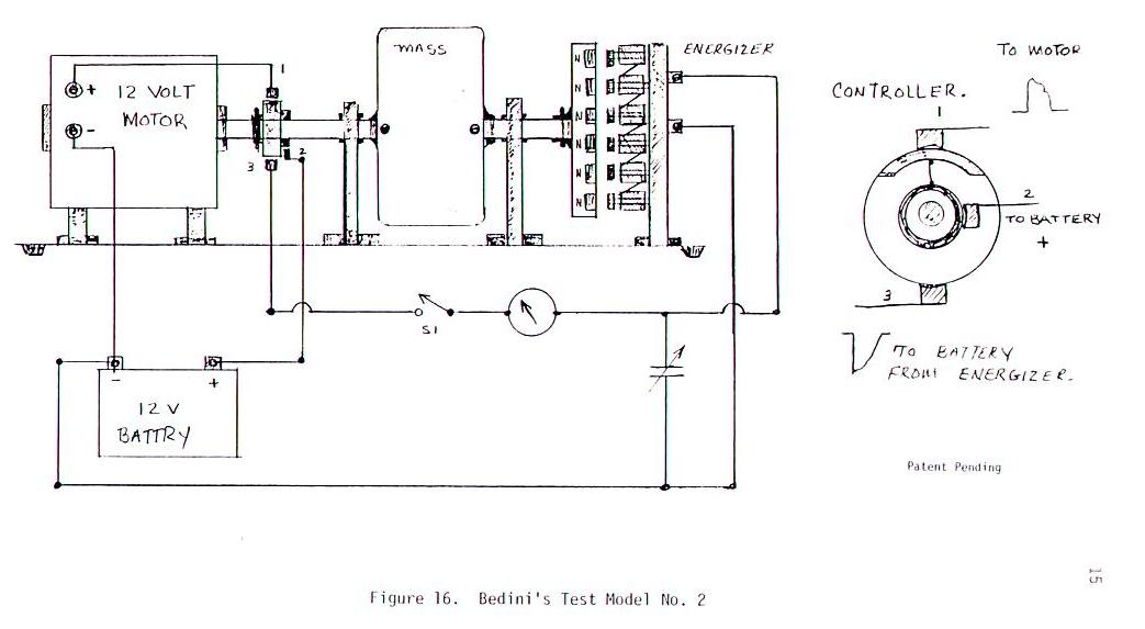
After looking at what Tom Bearden did in the book Electromagnetics part 4, This is what I did in 1984 to make the first model 2. I knew that it must be a switching and impedance problem, I also knew allot about pulse charging systems and what they did to the lead acid storage batteries . I also knew about charging batteries with huge Capacitor Banks. I was good at this because of the Amplifiers we were building at the time. You run into all kinds of Impedance problems and Phasing, so this was a piece of cake. I also knew about Mass weight and what flywheels did and how they stored energy. I figured that the generator could not be the normal kind because they were saying the word ENERGIZER which really means MAGNETO, but this did not answer the question of where the current came from, the Capacitor was the answer. The MAGNETO would charge this very fast and to High Voltages some times 10 times the battery voltage. When the machine first ran it would explode the batteries if they were bad, so I put the switch S1 to control it. When the battery would get low I would switch S1 to charge the battery back up. This was 18 years ago with what we have today this machine can be made real easy if you tinker with it and get it set right. The ENERGIZER How did I come up with this one you see in the picture. My uncle was a old time mechanic who was a real tinker, he use to tell me of the old lighting circuits just after the horse and carriage days and things that people would never believe, this is where My MAGNETO comes from. I told Jim Watson how to do this, I never thought that he would build a Machine that big but He did. and that's the story of this machine. Jim got paid off I got pushed agents the wall and told to by gasoline the rest of My life but once you see something like this you never give up.
In 1984 we could not just go down the street and by switching controllers, we just had to make are own from whatever parts we could find there were no Moss Fets no IBGT's just BI-Polar Transistors and some very good ones, but the easiest to do was a switched commutator as shown in the drawing which developed the most power with out loss. This machine worked the same way described in Gabriel Krons statements talking about the "OPEN and CLOSED paths.
This brings us to Kron's analogy said a different way.
When the Generator (MAGNETO) current becomes zero the circuit is self-supporting as the negative resistance of the circuit just supply the energy consumed by the positive resistance in the Capacitor. When the Motor current is positive the circuit draws energy from the Battery, and when the current is negative the Capacitor circuit pumps back energy into the source (Battery) this is known as” open-paths” and “closed-paths”. That discovery of open-paths established a second rectangular transformation matrix... into the Capacitor which created 'lamellar' currents. This circuit uses positive resistance in the Motor by an inductance and a negative resistance by a Capacitor bank collecting charge from the Magneto.What is it that I'm really saying?. I'm saying once the machine starts and is pulsed buy the controller, or commutator there is a switching taking place between the motor and the magneto using a capacitor that is being charged by the magneto in the OPEN path, while the motor is drawing a momentary current in a CLOSED path the two do not interfere with each other. So the magneto is something STATIC like a lighting bolt, just a CHARGE no real current. This is where the TRANSFORMATION takes place from STATIC to real useable current for discharge across the battery. The switching takes place and the capacitor discharges across the storage battery, but only to the level of the storage battery, so the level of the MAGNETO must be 5 times the battery voltage , the capacitor is now at the level of the storage battery and the process starts all over. Now you have KRON'S open and closed path system with no interacting grounds. If the battery is in good shape the impedance is around .0023 Ohms. If this is done fast enough and correct you will get a constant high current flowing to the battery, what the motor is using for power is not worth talking about. The system here can be done many ways this is just one.
DATE
: OCTOBER 13, 2000
BATTERY
TEST SEQUENCE:
One lead
acid gel-cell (12 volts, 450 milliamps) is being utilized as the primary source fully
charged at 12.5 volts.
Three (3)
lead acid gel-cell batteries (12 volt, 450 milliamps) strapped in parallel are being used
as the charge destination. The batteries are
discharged to 10 volts for the test purposes.
Test #1
starts at 10:45 AM utilizing primary battery fully charged at 12.5 volts charging three
(3) destination batteries paralleled. The
destination batteries reach a charge capacity of 14 volts at 11:20 AM.
Test
#3 starts at 1:00 PM utilizing primary battery measured at 10.5 volts. Charging three (3) destination batteries
paralleled. The destination batteries reach a
charge capacity of 14 volts at 1:40 PM.
12
lead acid gel-cell batteries (12 volts, 450 milliamps each). This ratio is a 12 to 1 charging factor. The motor operation (work) being performed as this
was done is not included as an additional factor in this test.
The chart above is the TUV test of the Highly Modified School Girl Motor dual battery system using standard Radio Shack Batteries off the shelf, never charging the batteries out of their packages. What was the purpose of the Monopole Motor posted on KeelyNet, in answer to that question it was to explain the technology of the Potential Charging of lead acid batteries and how this is done with a Back EMF, or Electrostatic energy. As simple as the School Girl Motor was it opened a gateway into the understanding of how to transform many of these electromagnetic pulses into real useable power for lead acid batteries, and many other type cells. In 1988 John Bedini set out to look at all the designs over the past years only to discover that the motor was the problem, the normal off the shelf motors were just not efficient enough. It was understood that in a system that must go over unity or a COP of 1 the motor being in a closed loop in the front end must be 99% or better.
NOTE: we never used the shaft power for anything except to turn a fan, or control timing.
(BTI) John started to developed motors running in this range, these were known to just transform the power into a potential charge without using any primary current, using just simple switching to do this. John then built about 147 different designs of this motor. At each design, John would call meetings with the investors and explain the system and how it worked, He then would summit to a testing of that system with out side consultants and reproduction of the system after the proper forms were singed.
John post to KeelyNet a simple drawing allowing anybody to make the design after Patents were filed with the US Patent office. John has always said that others need to know what the Technology is and how it works in the end. What John did not know was that others could not build it like John and did not understand the meaning of the experimental device. What was the meaning of the devices? The device was nothing more then a simple pulse motor with a One to One Transformer to collect Potential Charge in a Capacitor Bank without using any primary current to do it, to a voltage level for discharge across the secondary battery. What did the device teach us, It taught use a lot about what happens in lead acid batteries and how the lead acid battery could become the fuel cell of the future through just holding a Potential charge on the battery in pulses while the motor is out of the closed current loop. What John did with his experimental work was to show us at BTI, that you only need a "Electrostatic Potential" to charge the battery and the battery would recharge itself, and would sustain that charge in time longer then the normal charging of batteries.
NOTE: In Reviewing lab notes, John started his work on these systems in the 1960's while in the US Army, A quote from one of his friends Max, John always wanted to hook up a Motor to a Generator and have it run itself.
Gary Bedini BTI
![]()
![]()
Now returning to Kron's work where he is talking about a negative resistor, any potential charge of high voltage will force the dipole apart in a storage battery, or in any circuit correctly done to supply the energy to power itself . What does this mean for the storage battery, it means the lead ions can not move into a charge state or a discharge state, but the potential of the battery is there to be used and the universal dipole is supplying the energy to the circuit in a open system. one only needs to create only del-phi (Potential) waves and not currents of electron masses.
 Next Page this will take you to the old sight