The importance of the Homopolar Generator cannot be emphasized enough. It is a drag free generator that produces electricity by simply rotating a magnet in space!
Common generators will get bogged down when you draw electricity from them – for example if you light up a bunch of bulbs on a gasoline generator set, the engine has to work harder to compensate for that load, thereby burning up more gasoline.
But with a Homopolar Generator, you can draw electricity from it and it does not bog down what is turning the magnet. And this is just one of the many benefits of this kind of generator.
If you literally take a disc magnet and put a shaft through it, you can spin it and you will produce a voltage potential between the circumference of the magnet and the shaft that the magnet is rotating around. Think about it – you’re producing electricity by doing nothing more than rotating a magnet in space. There are no generator coils or anything like what is necessary in a normal generator! Simple, simple, simple!
This is all good, but the downfall is that you wind up with current, but almost no usable voltage and this has been the case since Michael Faraday first invented the Homopolar Generator, which was in fact the very first generator. This has been the case since 1831.
For nearly 200 years, the Homopolar Generator has been more of a novelty to most although a few low voltage high current applications have been powered by large industrial homopolar generators.
At the 2017 Energy Science & Technology Conference, I review the basic history and the most notable names who have been involved with this kind of generator and then I show a working model that I have used to charge some capacitors up to 150-160 volts! If you consider the fact that for the size of magnets I was rotating, I would be lucky to wind up with 0.5 volts! I have a neon bulb connected to the capacitor and the bulb blinks every time the capacitors are up to the trigger voltage of these neons, which is about 95-105 volts.
What this shows is that I’m able to get 200 TIMES THE VOLTAGE than is expected from this kind of generator, which could very well take the entire experimental world of homopolar generators to a whole other level of practicality unlike anything has ever been demonstrated. It appears that at the conference, the small demonstration model achieved a worlds record by showing that I have wound up with more voltage from a Homopolar Generator that anyone has achieved in the last two centuries!
This is VERY SIMPLE and I would encourage you to get a copy of this and experiment with it because even if you have very little technical knowledge, you can build this and make it work!
Part of the 2017 Energy Science & Technology Conference series (66 mins downloadable video).
The importance of the Homopolar Generator cannot be emphasized enough. It is a drag free generator that produces electricity by simply rotating a magnet in space!
Common generators will get bogged down when you draw electricity from them – for example if you light up a bunch of bulbs on a gasoline generator set, the engine has to work harder to compensate for that load, thereby burning up more gasoline.
But with a Homopolar Generator, you can draw electricity from it and it does not bog down what is turning the magnet. And this is just one of the many benefits of this kind of generator.
If you literally take a disc magnet and put a shaft through it, you can spin it and you will produce a voltage potential between the circumference of the magnet and the shaft that the magnet is rotating around. Think about it – you’re producing electricity by doing nothing more than rotating a magnet in space. There are no generator coils or anything like what is necessary in a normal generator! Simple, simple, simple!
This is all good, but the downfall is that you wind up with current, but almost no usable voltage and this has been the case since Michael Faraday first invented the Homopolar Generator, which was in fact the very first generator. This has been the case since 1831.
For nearly 200 years, the Homopolar Generator has been more of a novelty to most although a few low voltage high current applications have been powered by large industrial homopolar generators.
At the 2017 Energy Science & Technology Conference, I review the basic history and the most notable names who have been involved with this kind of generator and then I show a working model that I have used to charge some capacitors up to 150-160 volts! If you consider the fact that for the size of magnets I was rotating, I would be lucky to wind up with 0.5 volts! I have a neon bulb connected to the capacitor and the bulb blinks every time the capacitors are up to the trigger voltage of these neons, which is about 95-105 volts.
What this shows is that I’m able to get 200 TIMES THE VOLTAGE than is expected from this kind of generator, which could very well take the entire experimental world of homopolar generators to a whole other level of practicality unlike anything has ever been demonstrated. It appears that at the conference, the small demonstration model achieved a worlds record by showing that I have wound up with more voltage from a Homopolar Generator that anyone has achieved in the last two centuries!
This is VERY SIMPLE and I would encourage you to get a copy of this and experiment with it because even if you have very little technical knowledge, you can build this and make it work!
High Voltage N Machine, Advancing the Homopolar Generator by Aaron Murakami
In 1831, Michael Faraday invented the Faraday Disc Generator. It was a simple copper disc rotating between 2 magnetic fields that were perpendicular to the conductor. It worked, but had efficiency problems with current moving in opposite direction away from the magnetic field as well as other issues.
Around 1977, Bruce DePalma invented the “N-Machine”, which was not predicted by Faraday or Maxwell as it had the magnets FIXED to the conductor and they rotated together – something that is not supposed to work but it does.
N-Machine
Today, there is still no satisfactory answer as to why it works and the conventional explanations fall flat.
DePalma’s presentation is available here as part of a large collection of videos called Classic Energy Videos
Later on Adam Trombly enhanced DePalma’s N-Machine and was given two gag orders by the Pentagon. Fortunately, the patent applications had already circulated world wide and Paramahamsa Tewari had replicated Trombly’s machine and to this day, they are still moving this technology forward.
The above mentioned machines of DePalma, Trombly and Tewari are legitimate “overunity” machines where more electricity can be taken from it than is required to run the prime mover.
The problem with many of these related machines is that they output a lot of current, but there is hardly any voltage. The voltage is so low it will be in the millivolts and to get anything in the couple volt range requires very large setups with very high RPM’s.
At the 2017 Energy Science & Technology Conference, I’ll show the simplest and most elegant innovation to the N-Machine concept that has allowed me to charge a capacitor to 18 volts DC and the magnets are only 2 inches in diameter and they were spinning at only 2000 RPM at the most. This is a world’s record and is something that I came up with many years ago.
I’ve experimented with it off and on over the last few years and proven it to work indisputably and it is so simple that everyone will be wondering why nobody else has every figured this out until now.
This presentation will be the first presentation Saturday morning at the energy conference. All the seats are sold out, but the presentation will be released in the A & P Electronic Media catalog not too long after the conference.
For anyone that has followed Eric Dollard‘s work relating to Tesla and even Eric’s relationship with Chris Carson, many are interested in the electrostatic rotary converter built by Chris but very few know anything about it.
Here is Eric Dollard’s description as far as the content or sequence of the presentation (the 4 points below):
OBJECTIVE – A completely electro-static system of electric power, that is, non electro-magnetic, and free of any magnetic currents or materials, and its application to the Tesla Turbine.
DEVELOP – A practical electrostatic machine for the generation of electric power at the kilowatt level.
DEMONSTRATE – An operating electrostatic machine for the measurement of operating characteristics.
ESTABLISH – A suitable mathematical analysis to facilitate the engineering of an electrostatic induction machine.
This presentation will show you that the genesis of this reactionless, electrical generator, is John G. Trump during the time he was at MIT and was mentored by the famous Van de Graaff. Trump’s thesis was entirely on this subject and Van de Graff turned him on to the importance of using a vacuum as a dielectric to achieve very high voltage potentials at very narrow gaps. The MIT documents show that the claims are that this generator in a vacuum and under a load is “over 99% efficient” and that with larger builds, it can “exceed those efficiencies”.
Needless to say, that should capture the interest of anyone with a heartbeat. There have been multiple developers who have patented various iterations of this kind of generator over the years and one in particular appears to be virtually identical to what Chris Carson made. Eric Dollard is analyzing the mathematics involved based on Trump’s math and some equations from the patents in order to see who might be correct according to experimental evidence.
The first half of the demonstration, I cover the background story and then the second half, Eric covers the technical aspect of this generator. I follow up with a demonstration of the Carson generator, which is the worst case scenario. It is not in a vacuum, it doesn’t even have bearings but bushings. The rotary plates are put together by press-fit instead of being keyed and the nuts holding the shaft at both ends loosen or tighten up by the vibration. It’s a miracle it even made it through the conference.
When a motor spins the out of phase capacitor plates after it is excited with a few thousand volts, a sinewave is produced on the output of a step down transformer. When power is extracted from the output, it does not diminish the electrostatic charge on the capacitor, it is created by varying the capacitance between both halves with respect to time. This is all under the umbrella of parameter variation. It is known that in vacuum with minimal leakage (the demo unit having maximum leakage), that it takes an extremely long time before the charge has to be restored if at all. That is the self-sustaining aspect that Chris Carson found, Trump claimed as well as some patent holders of different variations of Trump’s generator.
Finally, you will know most of the full story behind this rotary electrostatic converter that many people have wondered about over the years and now you have it. The presentation also shows several covers to different papers by Trump including his thesis and a patent that are must have’s in order to delve deeper into the study of this machine. This is far from definitive because many experiments need to be done, a higher quality and more robust rotary capacitor needs to be built to run in a vacuum chamber – so have at it – you now have the keys to a truly reactionless generator where drawing a load from it does not reflect back to the prime mover and this is potentially, a Holy Grail generator once fully optimized.
A new batch of 24 Lakhovsky Multiwave Oscillators, Model MD-1G/UA, is being hand built right now at A & P Electronic Media in Spokane, Washington. Pre-orders are open: paid in full, first come, first served, and units ship in the order the orders came in, with shipping expected the second week of January 2027.
Get the current Price List and Order Documents
They are free through a no-charge checkout on the product page. The PDF downloads the moment you check out.
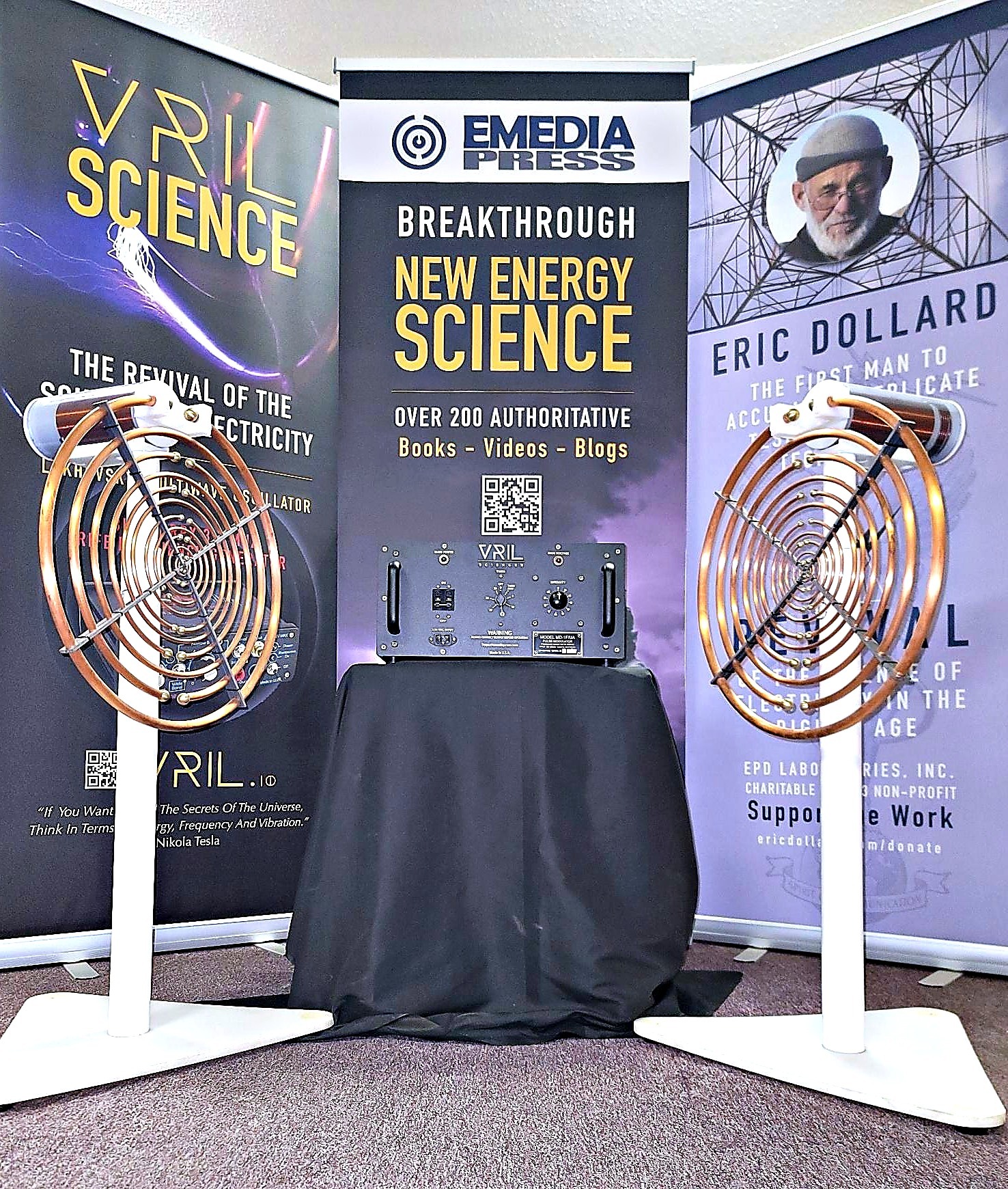
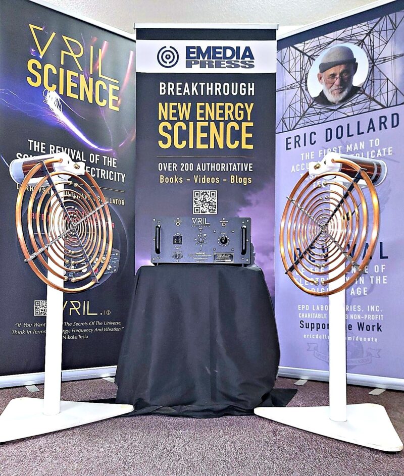
The full MD-1G/UA system with copper ring antennas.
Built from the original machines, not the patent
The Lakhovsky Multiwave Oscillator has been copied many times. Most copies reproduce the look of the machine, the concentric rings, and skip the details of the surviving original instruments. That changed around 2012, when European engineers reverse-engineered surviving original MWOs and published a report on how they were built.
Our machine is built from that work. It is not built from a patent drawing or a photograph, and it is built and sold as a research instrument. It is one of only two electrically correct replications being made.
What electrically correct means
An authentic MWO is defined by three inherent imbalances: the coils have differing numbers of turns, they sit at unequal distances, and one phase is grounded. None of the three shows up in a photograph, and none of them is in the patent. A copy that starts from the patent or from the appearance gets them wrong, and the result is a different circuit wearing the same rings. The transmitting side, the receiving side, the grounding and the spark gap are one electrical system, and the relationships between them are the design.
Copper rings or Eric Dollard’s Golden Ratio antennas
Two antenna systems are available, and both run on the same pulse modulator:
Copper ring antennas, bent to Lakhovsky’s BV2 specifications.
Golden Ratio PCB antennas, designed by Eric Dollard.
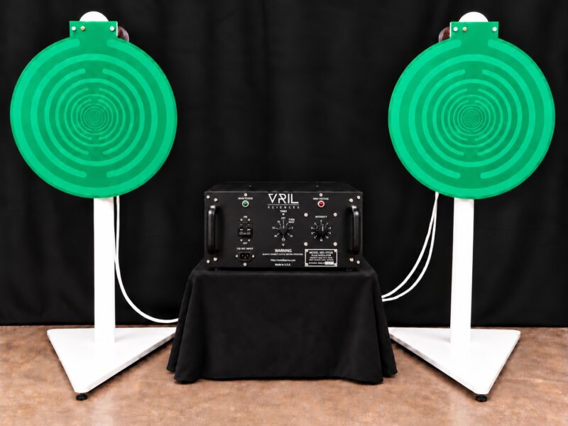
The MD-1G/UA with Eric Dollard’s Golden Ratio PCB antennas.
The pulse modulator and its adjustable quadruple spark gap produce the high-voltage, broad-spectrum output the original design calls for. The MD-1G/UA is the seventh generation of the system since production began in 2017 and 2018.
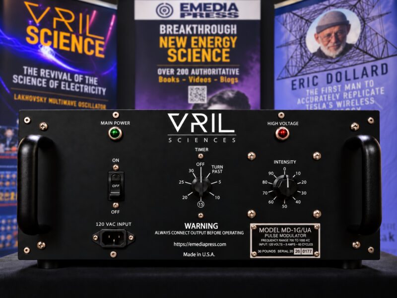
The MD-1G/UA pulse modulator, front panel.
Two ways to connect it
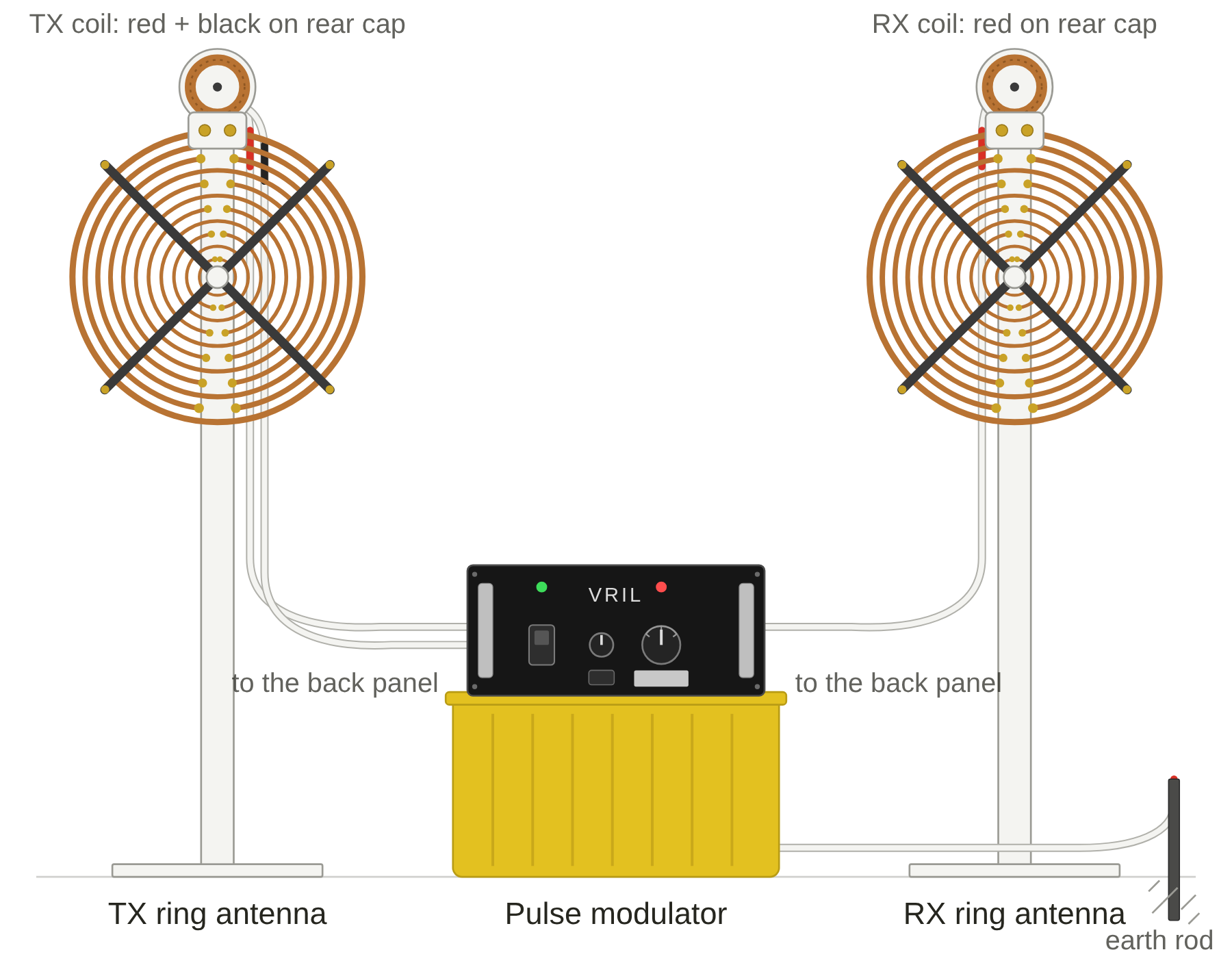
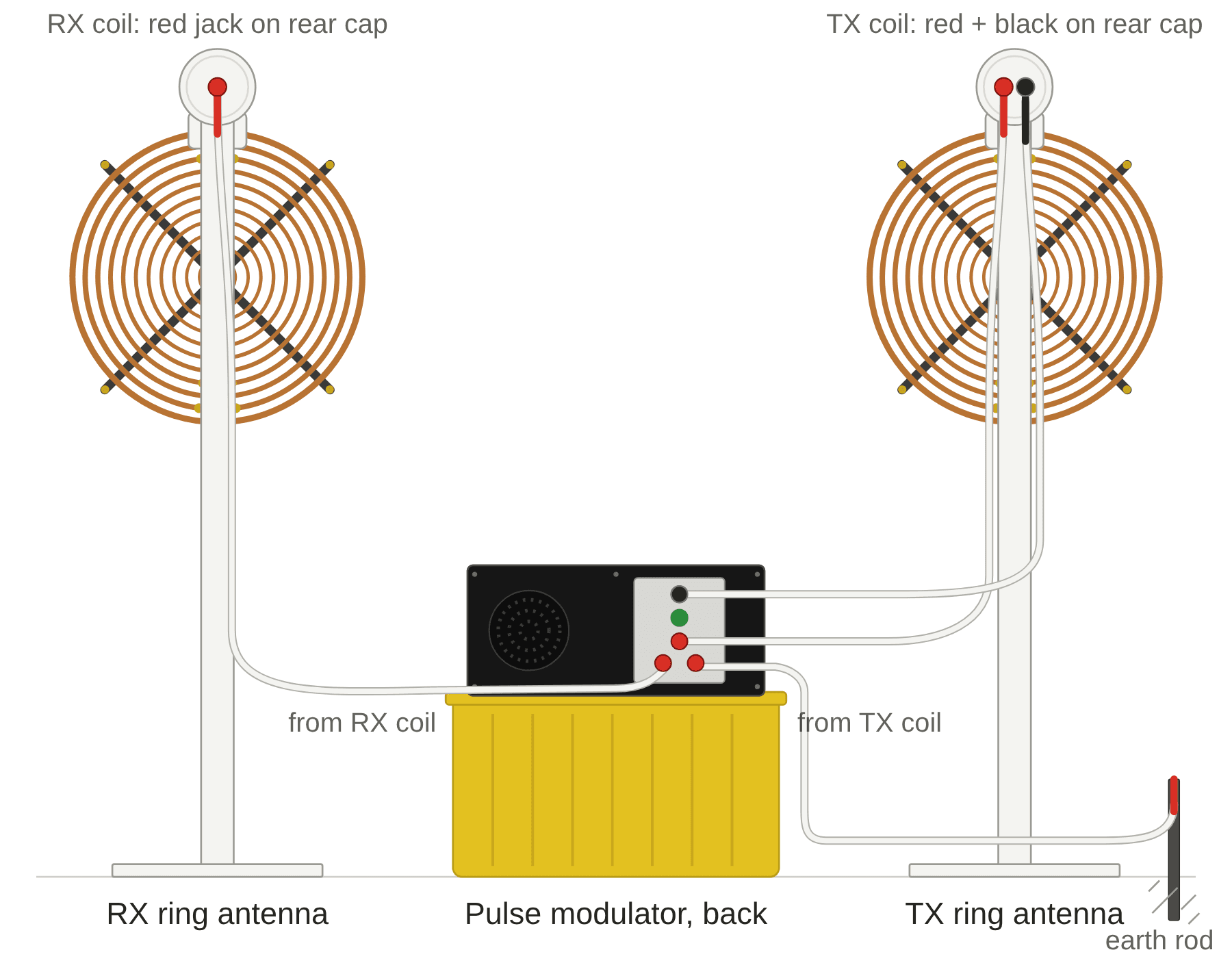
Default unbalanced Lakhovsky mode is the standard Lakhovsky configuration, with the cables running to the back of the pulse modulator.
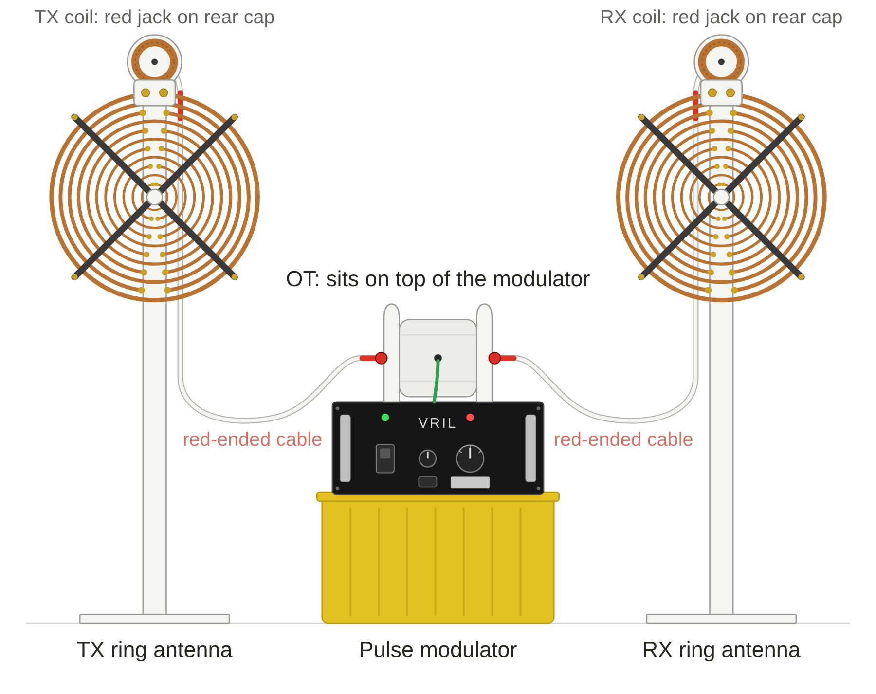
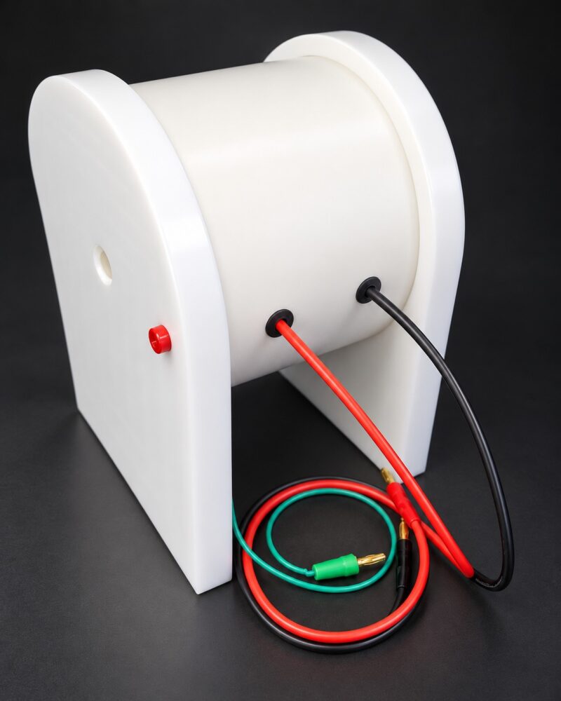
Balanced Tesla-Dollard mode puts the oscillation transformer on top of the modulator as a balanced, centre-tapped primary, bypassing the primary on the transmitter coil. It is a different experimental arrangement, built on Tesla’s and Eric Dollard’s work.
Hookup A1: unbalanced mode, front view.Hookup B1: balanced mode with the oscillation transformer, front view.
The product page has all six hookup diagrams, three for each mode: from the front, from behind and at the back panel. See all six MWO hookup diagrams.
Check out at no charge. The PDF downloads immediately, and the link is also in your order email.
Read the price list and fill out the Order Documents completely.
Return them and pay in full as the documents describe.
Orders are handled in the order they are received, and units ship in that order. Every MD-1G/UA carries a one-year repair-or-replace guarantee. Power outside the US, what is included and shipping are covered on the product page and in the Order Documents. For anything else, use the contact form and I will answer you myself.
The oscillation transformer used in balanced Tesla-Dollard mode.
Back in 2007 I filmed a little demonstration — a completely self-running, closed-loop Bedini SG oscillator built around a trifilar coil. No batteries in the loop… just capacitors that keep charging themselves indefinitely while the system runs at a voltage far below what the transistor is “supposed” to need.
Watch the newly re-uploaded video here (details below the video):
What you’re seeing:
Classic trifilar Bedini SG coil (23-gauge, ~2,000 turns): power, trigger, and one completely isolated recovery winding
RCA 3055 transistor (yes, the old-school one)
Front-end powered only by capacitors that are being conditioned with a high-frequency, high-voltage relay/ignition-coil pulse circuit
Recovery energy from the isolated winding is fed straight back to the input capacitors — the input side literally cannot “see” the output side – if it did, it would wind down fast and defeat itself
A simple ground rod connected to the circuit (just like John Bedini showed on the original 1990s KeelyNet schematics)
The result? The input capacitor drops a little at start-up, then climbs back up and just… stays there. I left it running for a long time until I literally got bored. The system stabilizes and oscillates forever on its own recovered energy — and it does it while running on less than a volt, way under the official transistor spec. That alone tells you something very non-conventional is happening with the current.
John Bedini always insisted the earth ground made the machine “run stronger.” Most builders ignored that detail. This demo proves he was right — you can see the dramatic difference the moment the ground rod is connected.
Those old original schematics that John originally posted are down below.
Why this matters in 2025
Two weeks ago I wrote about the Benitez self-running systems from the early 1900s. After personally witnessing multiple closed-loop devices over the years — including this simple oscillator — I’m no longer surprised that Benitez may have been telling the truth. In fact, when you study his patents side-by-side with some of the later “free energy” circuits that became famous, the family resemblance is unmistakable.
The real magic isn’t in complicated hardware. It’s in understanding switching, energy recovery, conditioning (caps or batteries), and the role of the local environment (yes, including that ground rod most people leave out).
The treasure trove awaits you
Everything I’ve learned over decades — plus thousands of posts, photos, scopes shots, and complete build details from John Bedini, Peter Lindemann, Eric Dollard and many others — lives inside Energetic Forum.
We’re actively posting new material again, and some of the most exciting SG-related projects I’ve been working on behind the scenes will start appearing there first.
Join today — it’s 100% free, approvals happen several times a day, and you’ll instantly get access to gigabytes of the most authoritative open-source material on the planet for these topics.
Come share your thoughts, your builds, and your questions. The forum is alive again — and the next wave of breakthroughs is going to come from builders like you
Long before modern electronics, inventors like James Wimshurst were exploring how nature separates charge… It was the heart of early X-ray experiments and high-voltage demonstrations—and an early example of what we might now call an open system, pulling energy dynamically from its surrounding electric field. In the 1860s, physicist Poggendorff went a step further, creating the first corona motor—a device that used ionized air, not mechanical brushes, to push a rotor. More than a century later, Oleg Jefimenko revived that work to show that electric fields themselves can do mechanical work directly, bypassing the conventional closed-circuit model of electricity. Those classic experiments are the foundation for much of today’s exploration into electrokinetic and open-energy systems. That’s the legacy our students tapped into—literally by hand—at the fair.
Designing the Demonstration
I designed and built the demonstration system with assistance from the students, prepared the Wimshurst generators, and helped set up the components for the presentation. During the setup period I spoke with teachers, students, and visitors about how the devices operate and about their significance in exploring open-system physics—where charge, field, and motion interact continuously with the environment. I explained how the work of pioneers such as Oleg Jefimenko, John G. Trump, and later experimenters like Eric Dollard and Chris Carson helped extend this field of study. Carson’s self-sustaining high-voltage electrostatic rotary converter, inspired by Trump’s MIT research, demonstrated the same basic principle: energy can circulate through the electric field itself rather than being consumed. We also discussed the remarkable Testatika machine built by Paul Baumann of the Methernitha Christian Community in Switzerland—a large Wimshurst-type generator said to power their facilities through similar electrostatic processes. While I handled much of the technical design and preparation, the students themselves conducted the official presentation before the judges, in keeping with the competition’s rules. Their confidence and understanding showed that they truly grasped what they were demonstrating.
Building the Machines
We used two Wimshurst generators: one commercial unit and one that I constructed from locally sourced materials—polycarbonate discs, aluminum sectors, brass combs, and Leyden jars made from plastic tubing and foil. Both produced visible sparks several centimeters long. For the second exhibit, we built a corona motor using an empty soda can as the rotor. The can’s rim had several tiny tangential holes sanded to bright aluminum, mounted on a stainless-steel marinade-injector needle pivot connected to one of the Wimshurst terminals. Opposite the can, a sharp sewing needle, connected to the other terminal, was aimed just off tangent to the can’s surface. When the Wimshurst machine spun up, faint bluish plumes of corona discharge arced from the sewing needle toward the can. The invisible ion wind pushed air along the can’s surface, producing pure electrostatic thrust. The can began to rotate—first hesitantly, then faster and smoother—powered entirely by electric-field interactions. No magnets. No moving coils. Just field, air, and geometry.
The Demonstration
During the judging, Emmanuel, Sheenaia, and Vivian operated the Wimshurst machines and demonstrated the corona motor to the panel. Two neon bulbs connected to the terminals flickered orange with each charge pulse, showing the potential difference across the Leyden jars. As the can rotated, they brought it near an aluminum backplate. Immediately, the can was attracted to the plate—a vivid display of electric-field interaction—and the corona brightened to a deep violet glow. The audience could see and hear electricity in motion. Teachers leaned in, students gasped, and judges nodded appreciatively. The excitement in the room was palpable as they witnessed a nineteenth-century principle come alive again through twenty-first-century craftsmanship.
Beyond the Sparks
What made the project stand out was that it revealed open-system behavior in a tangible, student-friendly form. Unlike ordinary circuits that consume stored charge, the Wimshurst and corona motor are self-recharging systems that draw and separate charge directly from their surroundings. They invite students to think beyond conventional energy models—to ask where the “push” really comes from, and how fields themselves can store and exchange energy dynamically. Every hiss from the corona and every pulse from the Leyden jars reminded the students that the universe is not inert—it is an active electrical medium waiting to be understood.
Inspiring the Next Generation
When our team’s name was announced for 2nd Place, the students’ excitement said it all. Dozens of others gathered afterward to ask how to build their own machines. Teachers expressed interest in future workshops, and local officials congratulated the group for reviving curiosity about classic high-voltage experiments. For me, the real reward was watching young people realize that science is still full of mysteries worth exploring. You could see it in their expressions—the moment they recognized that even a simple hand-cranked machine could unlock questions about the nature of energy itself.
Looking Ahead
We plan to expand our work with larger electrostatic systems and explore continuous-operation versions powered by modern high-voltage supplies. There is a vast field of discovery waiting in the interplay between electrostatics, induction, and resonance—territory that pioneers like Jefimenko, Trump, Dollard, Carson, and Baumann have already begun to map. Alternative-energy research doesn’t always require exotic materials or expensive laboratories. Sometimes it just needs a soda can, a crank, and the courage to look at electricity differently.
Epilogue
The Misamis Oriental Science Fair was more than a competition—it was proof that when curiosity meets craftsmanship, even century-old ideas can feel revolutionary again. Our students demonstrated that high-voltage electrostatics, far from being obsolete, can still capture imaginations and open minds to the broader possibilities of open-system energy research. As we packed up that day, a few last sparks jumped between the terminals of the Wimshurst machine—small, fleeting, and beautiful, like the moment of discovery that started them.
About the Author
Ed Becnel is a retired software engineer who earned a Bachelor of Science degree in Electrical Engineering. He has been keenly interested and involved in alternative-energy and overunity research for many years. Originally from Louisiana, Ed relocated to the Philippines in 2021, where he continues to mentor young students in experimental science and engineering. He is currently collaborating with colleagues in the U.S. on various projects related to alternative energy production and utilizationr.
Author: Ed Becnel Mentor, Misamis Oriental National High School With students Emmanuel Bongcas, Sheenaia Cabanig, and Vivian Aboc Tagoloan, Misamis Oriental – October 2025
100% Electrically Correct Lakhovsky Multiwave Oscillator (MWO) – For Research Use Only
The Vril Lakhovsky Multiwave Oscillator (MWO), manufactured by A & P Electronic Media in Spokane, Washington, USA, is a high-voltage, high-frequency device engineered for researchers, engineers, and hobbyists dedicated to exploring longitudinal waves and displacement currents. As part of the Vril product line, this MWO is one of only two authentic, verifiable replications of Georges Lakhovsky’s original design worldwide, the other crafted by a trusted colleague in Croatia. Unlike countless mislabelled imitations, this device is 100% electrically correct, grounded in a 2012 reverse-engineering breakthrough by European engineers that unveiled Lakhovsky’s true design after decades of speculation. It generates longitudinal waves transmitted between its antennas via electrostatic propagation, producing a displacement current distinct from conduction current, with three critical imbalances defining its authenticity. Sold exclusively for research purposes, no claims are made about its effectiveness.
Pre-orders open: a new batch of 24
24 units of the Model MD-1G/UA are being hand built in Spokane, with shipping expected the second week of January 2027. All pre-orders are paid in full and filled first come, first served: units ship in the order the orders came in.
How to get pricing and order:
Click Get FREE Price List & Order Docs to add the free PDF to your cart.
Check out (no charge).
Download the PDF to see current prices and the order documents.
When you are ready to order, fill out the order form and documents, scan them and email them to the address printed on the order form.
You will receive a reply with payment instructions. That’s it.
One-year repair-or-replace guarantee. Sold for research use only. Hand built by A & P Electronic Media in Spokane, Washington, USA.
Model MD-1G/UA
The Vril Lakhovsky Multiwave Oscillator (MWO), model MD-1G/UA, represents the pinnacle of A & P Electronic Media’s engineering prowess, now in its seventh generation since production began in 2017–2018. Manufactured in Spokane, Washington, USA, under the prestigious Vril product line, the MD-1G/UA, where MD stands for Modulator, 1G denotes the first model’s seventh iteration, and UA signifies Invisible Rays, per authentic U.S. Navy abbreviations, embodies a 100% electrically correct replication of Georges Lakhovsky’s original design, refined through years of relentless innovation in manufacturing processes. This cutting-edge device, one of only two authentic MWOs worldwide, delivers unparalleled performance for researchers exploring longitudinal waves and displacement currents, cementing its status as a groundbreaking tool in frequency research.
Vril: Authentic Lakhovsky Legacy
The Vril Lakhovsky Multiwave Oscillator (MWO), produced by A & P Electronic Media, is a cornerstone of frequency research, delivering a 100% electrically correct replication of Lakhovsky’s original machine. Until around 2012, every device claiming to be an MWO was speculative; Lakhovsky’s production units remained an enigma. European engineers changed this by reverse-engineering surviving MWOs, publishing a report that revealed the true design, debunking underpowered, balanced units with no connection to Lakhovsky’s vision.
An authentic MWO is defined by three inherent imbalances, engineered by Lakhovsky to maximize harmonic generation through frequency clashing:
Differing Coil Turns: The transmitting (TX) coil’s secondary has a slightly different number of turns than the receiving (RX) coil’s secondary, creating wave asymmetry.
Unequal Coil Distances: The transmission distance from the primary coil (on the TX side) to its secondary is tightly coupled but the distance from the primary to the RX secondary is over multiple feet, enhancing harmonic dissonance.
Grounded Phase: One phase is grounded, forcing emissions to split, partially reaching the opposite antenna and partially driving flux downward to ground, crucial to Lakhovsky’s design, unlike balanced units where emissions form a closed loop, “bathing” anything between the antennas.
Devices lacking these features are inauthentic and misrepresent Lakhovsky’s legacy; they have no right to his name. Only A & P Electronic Media (via Vril) and the Croatian manufacturer produce true MWOs.
This MWO can produce up to hundreds of thousands of volts, with an adjustable, quadruple spark gap facilitating the transmission of longitudinal waves via electrostatic propagation. Its development reflects a unique genealogy: Bob Beck popularized the MWO through talks, George Van Tassel’s Integratron was inspired by it, Peter Lindemann and Eric Dollard studied speculative MWO theories at Borderlands (without a working unit), and Paul Babcock built a homemade version from the 2012 report. Inspired by Babcock’s unit, A & P Electronic Media produced it, with input from Lindemann and design/refinement by Dollard, who created the Golden Ratio PCB antenna. Beck’s past funding of Dollard and Dollard’s Integratron work add to this unmatched lineage.
Assembly takes ~10 minutes with one person, with a walk-through tutorial available for ring/PCB antenna and oscillation transformer use. This video shows the ring antenna setup, the PCB antenna setup and the oscillation transformer setup.
Never turn on the pulse modulator unless the antenna cable system is fully hooked up and plugged in.
Default: unbalanced mode
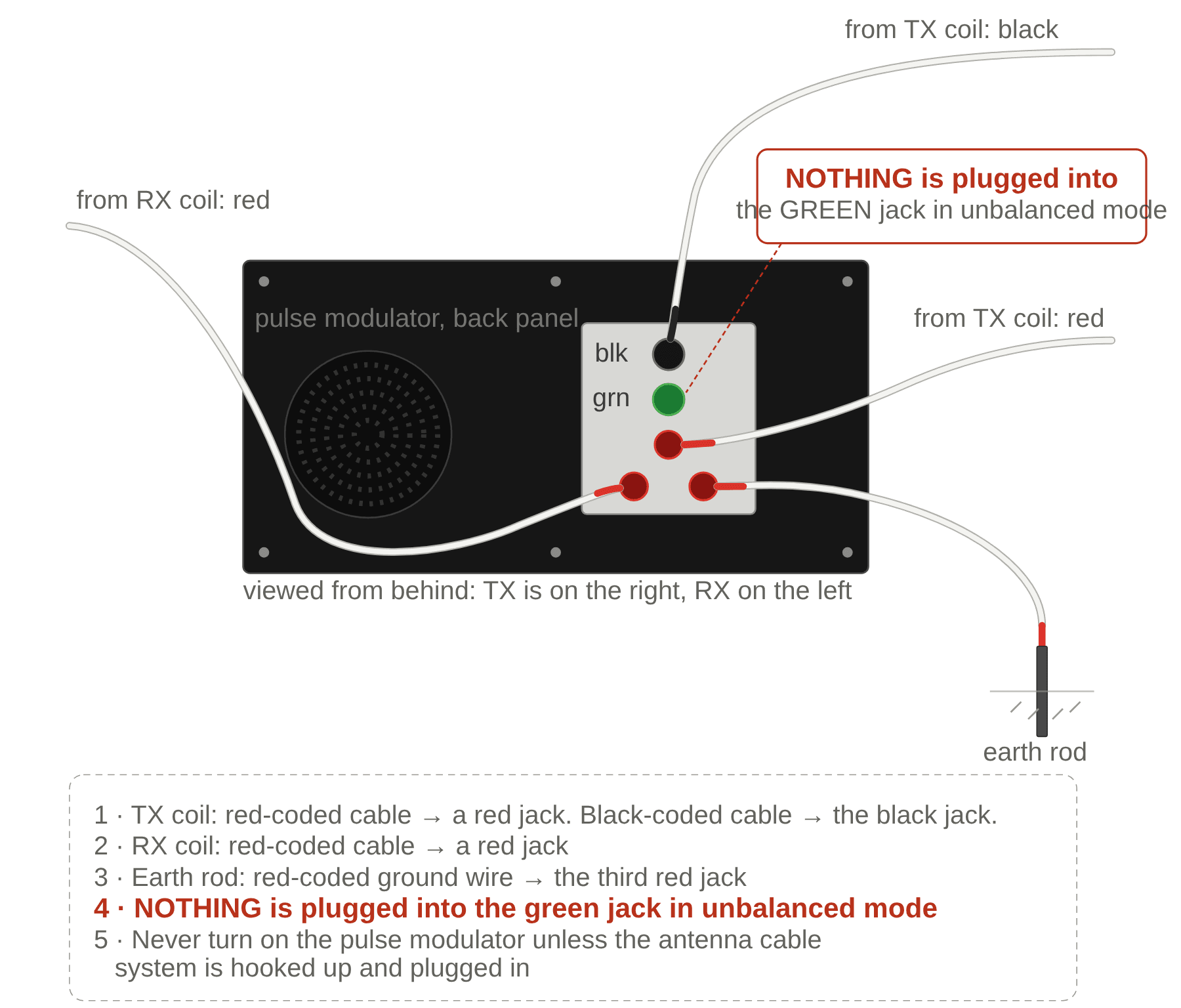
No OT. Both coil cables run straight to the back of the pulse modulator, plus a ground wire from an earth rod. Nothing goes in the green jack.
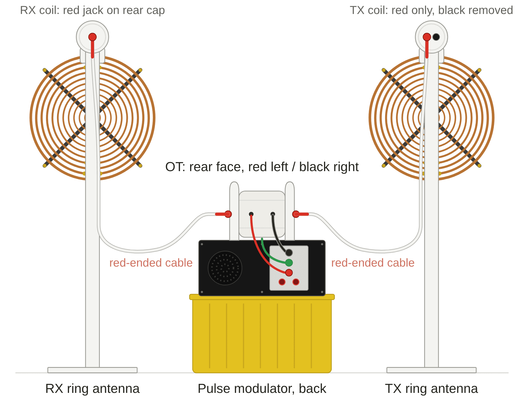
A1: Unbalanced, front view. Cables run to the back of the modulator.A2: Unbalanced, from behind. Rear caps, plugs, and the cables landing on the back panel.A3: Unbalanced, back panel. Green jack stays empty.
Balanced mode: with the oscillating transformer
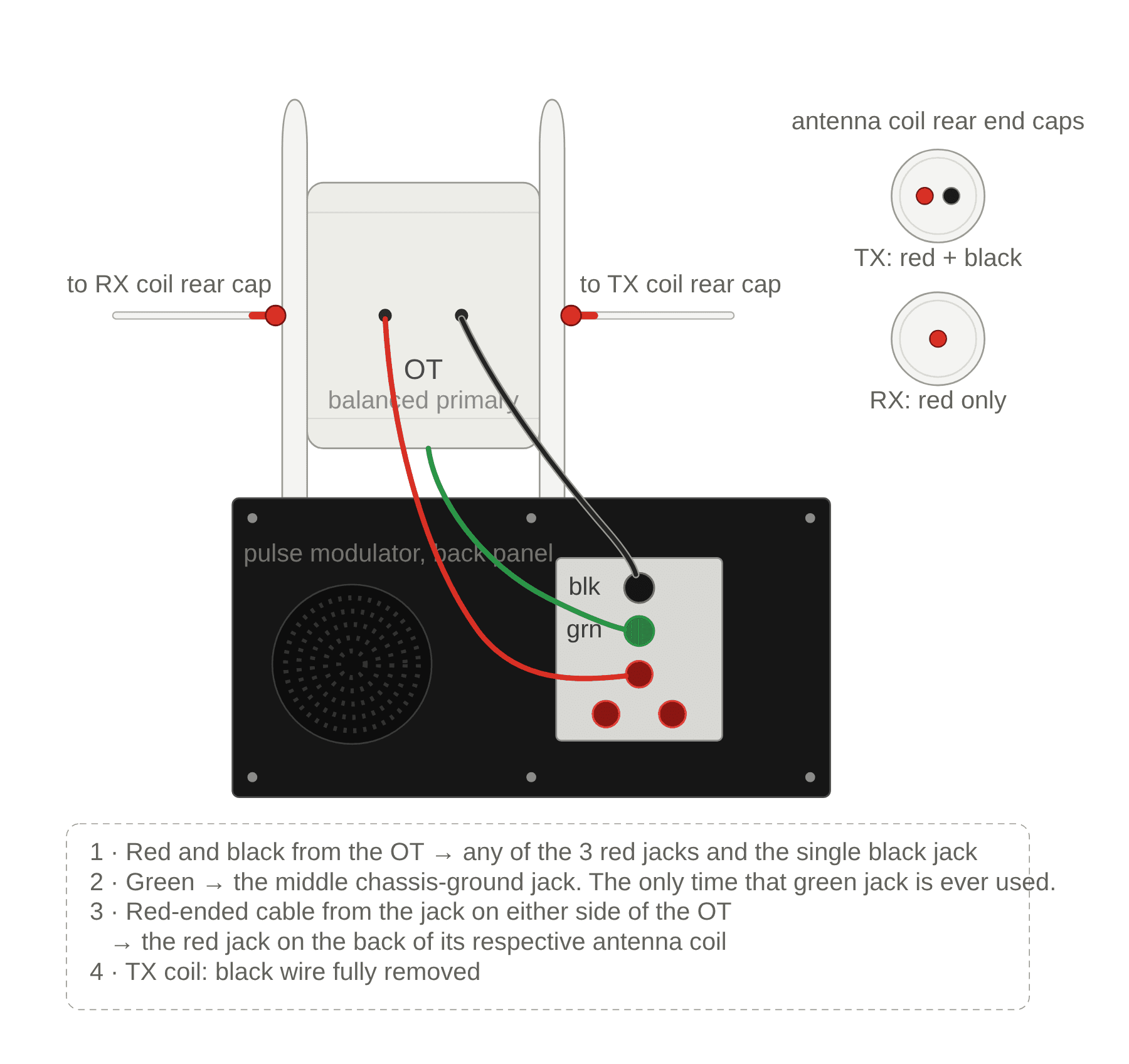
The OT sits on top of the modulator as a balanced, centre-tapped primary, bypassing the primary on the TX coil.
B1: Balanced, front view.B2: Balanced, from behind. OT on the modulator, everything landing on the back panel.B3: Balanced, OT to back panel. Rear view.
What’s Included:
1 x Pulse modulator
1 x Cable set
2 x stand platforms
2 x upright stand poles
1 x TX coil (with mounting for either copper ring or pcb antenna)
1 x RX coil (with mounting for either copper ring or pcb antenna)
2 x Copper Ring OR PCB Antenna
OPTIONAL – Oscillation Balanced Transformer
OPTIONAL – 120VAC, 60Hz, True Sinewave Inverter (to run the MWO in 50Hz countries from a 12v deep cycle battery)
NOTE: The PCB version costs less than the ring antenna version but the power cannot be turned up as much because it can cause too much corona that will break down the masking on the PCB antenna.
The True Design Rediscovered Historical Context
Georges Lakhovsky was captivated by high-voltage electrostatic phenomena, experimenting in the early 1900s with oscillating frequencies to explore effects on plants and soil conductivity. Using the Earth-ionosphere voltage gradient (~100 volts/meter), he grounded plants with copper rings, observing responses that fuelled his curiosity. This curiosity led to the Multiwave Oscillator, generating longitudinal waves via electrostatic propagation even though he may not have understood the nature of these waves. Numerous online resources detail Lakhovsky’s work for further study. His production machines diverged from his patent, misleading imitators who built inauthentic variations.
The 2012 reverse-engineering report was a breakthrough, revealing the three imbalances: differing coil turns, unequal coil distances, and a grounded phase. The grounded phase, driving flux to Earth, set Lakhovsky’s design apart from balanced units with closed-loop emissions. These details, absent from the patent, were unknown until then, exposing prior replicas as incorrect. The Vril MWO brings this authentic design to researchers, with historical references for educational purposes only.
Grounding cable goes to back of pulse modulator phase 2 connection and into the ground on an outlet (dedicated ground rod is best).
The Vril MWO is engineered for studying longitudinal waves and displacement currents, offering:
High Voltage Output: Up to hundreds of thousands of volts, with an adjustable spark gap for transmitting longitudinal waves via electrostatic propagation between the antennas.
Antenna Options:
Copper Ring Antenna: Bent to Lakhovsky’s BV2 specs; coil mounting adapted for rings.
Golden Ratio PCB Antenna: Designed by Eric Dollard; coil mounting adapted for PCBs.
Coil Design:
TX secondary: Different turns than RX secondary.
Primary-to-secondary distance varies between TX and RX.
Multiple layers of dielectric coating protect high-voltage windings.
Grounded Phase: Splits emissions, part to the opposite antenna and part to ground, forcing flux downward.
Stands: Two platforms and two upright poles, furniture-grade tubing for looks and stability.
Oscillation Transformer: Optional, engineered by Dollard, for balanced mode experiments like the Cosmic Induction Generator.
Power Requirements: 110V 60Hz; optional inverter for overseas use.
Assembly: ~10 minutes with one person; walk-through tutorial YouTube video posted above.
1-Year Guarantee: Repair/replace within one year; no-refund policy, voided if opened without authorization. After 1 year, we can repair/replace very close to our actual cost.
Lakhovsky MWO with copper ring antenna
Lakhovsky MWO with PCB Antenna
Research Applications
The Vril MWO is ideal for experiments with longitudinal waves and displacement currents in different systems:
Plant Studies: Explore grounded flux effects on growth or conductivity, inspired by Lakhovsky’s copper-ring tests, contributing to electroculture research.
Water Research: Investigate resonance or structuring driven by downward flux, probing electrostatic interactions with aqueous systems.
Harmonic Analysis: Study clashing harmonics from the three imbalances, using oscilloscopes or spectrum analyzers for philosophical or recreational insights.
Electrostatic Exploration: Experiment with electrostatic propagation, leveraging the grounded phase to study wave behavior in gases, solids, or other media.
Users must comply with all applicable laws and understand local regulations where the device is operated, ensuring responsible research practices.
Damaged plant before exposure to MWO – Jelmer U., Netherlands
Plant is thriving 24 days after exposure to MWO – Jelmer U., Netherlands
Technical Specifications
Output Voltage: Up to hundreds of thousands of volts.
Waveform: Longitudinal waves with displacement current, via electrostatic propagation, driven by three imbalances, forcing flux to ground.
Frequency Range: Adjustable via spark gap and antenna.
Antenna: Copper rings (BV2) or Golden Ratio PCB, with adapted coil mounting.
Materials: Coils with multiple layers of dielectric coating; stands from furniture-grade tubing.
Power: 110V 60Hz; optional inverter for overseas use.
Why Choose the Vril MWO?
Unmatched Authenticity: One of two true MWOs, validated by the 2012 report.
Rich Genealogy: Rooted in Bob Beck’s popularization, George Van Tassel’s Integratron inspiration, Peter Lindemann and Eric Dollard’s speculative Borderlands studies, and Paul Babcock’s homemade MWO. Lindemann’s input and Dollard’s design (including PCB antenna and Integratron work) were key, with Beck’s past funding of Dollard adding to this unique lineage.
Research Focus: A tool for exploration, not guaranteed results.
Made by A & P Electronic Media: Crafted in Spokane, Washington, under Vril.
This MWO’s lineage, tied to Beck, Van Tassel, Lindemann, Dollard and Babcock, establishes it as the most authentic continuation of Lakhovsky’s principles, tracing back to when few understood the MWO.
Shipping/Transport Information
Shipped from Spokane, Washington, by A & P Electronic Media. Once a unit is complete, tested, and ready, it is transferred to Action the Shipping Depot for custom packing and shipping. Action the Shipping Depot contacts the customer directly to arrange and collect payment for packing and shipping; A & P Electronic Media does not handle this process.
Shipping Contact: Action the Shipping Depot (Your contact information will be provided to them when we deliver your items)
Options: Domestic (U.S.) via motor freight or FedEx; Canada/international via FedEx. Payment is managed between the customer and Action Shipping Depot. You are not required to use FedEx – you can choose any shipping company you wish.
International Orders: An International Invoice will be provided to Action the Shipping Depot. Customer is responsible
for any applicable VAT or tariffs in their country.
Antenna Storage: Free PDF design for a carry case provided by a customer: MWO Ring Box Plans
Disclaimer
The Vril Lakhovsky Multiwave Oscillator (MWO) is sold for Research Use Only. It generates longitudinal waves and displacement currents, and no claims are made about its effectiveness. Users assume full responsibility and must comply with all applicable laws, including understanding and adhering to local regulations where the device is operated.
This device is for personal enjoyment, philosophical research, or hobbyist experimentation (e.g., studying effects on plants or water). By purchasing, the buyer agrees to the no-refund policy and acknowledges it is sold as-is, with no guarantees or warranties, express or implied.
It is for research only and not for medical, clinical, or diagnostic purposes. No medical, curative, or wellness claims are made. It is not FDA-approved and cannot substitute for medical equipment.
To get pricing and order: click Get FREE Price List & Order Docs, check out (no charge) and download the free PDF.
Here’s the first of many new releases from the 2022 ESTC.
This one is an electrostatic generator invented by John G. Trump, the same Trump who was called in to analyze Tesla’s work after Tesla died. John Trump was mentored by Van de Graaff while at MIT and due to Van de Graaff’s encouragement to study vacuum high voltage systems, this generator concept is the result.
The test unit shown was built by Chris Carson, a friend of Eric Dollard’s and over the last year, we have figured out the basic running method, Eric has analyzed the math, I’ve been doing the bench experiments and have seen enough to realize that the claims by Trump and Carson are true.
The demo unit is flea power, is not in a vacuum so is not ideal but the presentation gives enough information for anyone to develop it further if they wish. There is no back EMF since there are no magnets or coils so when placing a load on it, the prime mover will not know.
This is Part 4 of Mike Clarke’s presentations on the Reactive Power Generator, which has advanced by leaps and bounds since its inception. At its essence, it is like a Bedini SG, but with multi air core coils, higher voltage and with automatic battery swapping.
The results? The input and output batts keep swapping and keep themselves charged up – it’s a true self-running motor that turns a generator that produces hundreds of net watts and again, the batteries stay charged up.
Due to a problem with an optical sensor used for timing, this machine did not run at the conference but worked just fine at Paul’s home shop the night before.
Mike shares how he is now making his rotor that is very inexpensive and faster than machining so the whole manufacturing process has been streamlined to the point that it is becoming practical on all levels, including financially.