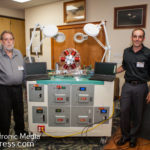
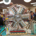
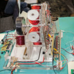
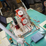
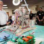
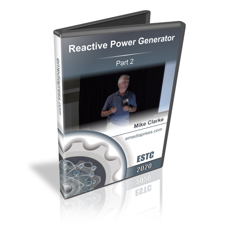
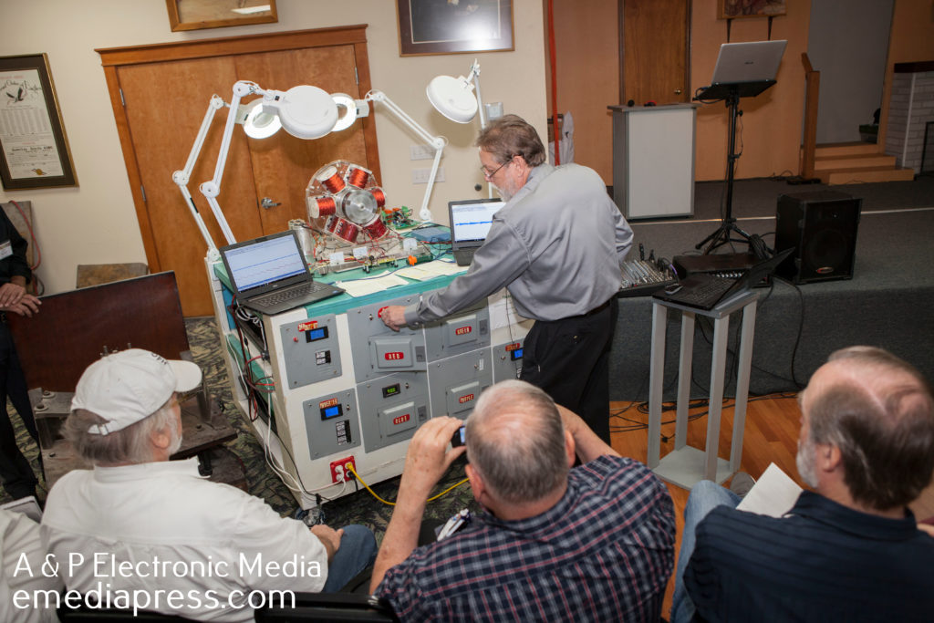
Last year, Mike Clarke presented on his RPG machine that he co-developed with his partner Norm and with the assistance of Paul Babcock. It ran for many months after one charge of the batteries and it has kept itself charged up ever since and that is with it running at thousands of RPM while the generator produces steady work.
This year, he presented on the Renaissance Motor developed by Norm but also gave more details on his tests with the RPG, which is essentially an air core Bedini SG scaled up and running on 60 volts. He shows some data on it running and how the batteries simply stay charged up. The principles are right there with the air core and higher voltages than most Bedini SG machines are run but this is the window that is necessary to start exploiting these methods that John Bedini has taught for years.
Part of the 2020 Energy Science & Technology Conference series (77 mins downloadable video).
At the 2016 Energy Science & Technology Conference, Peter Lindemann demonstrated a Bedini SSG energizer that produced a lot of mechanical work all weekend and the batteries stayed charged up!
It worked beautifully and was done with an automated circuit that rotates the batteries in a certain way but most people do not have the know-how to be able to build that circuit.
At this year’s conference, RS Stafford replicated this battery swapping method with circuit breaks and other common parts from his local hardware store. It’s inexpensive and very, very simple to build. This is the machine that ANYONE can make work if they just follow some simple wiring diagrams and RS’s instructions.
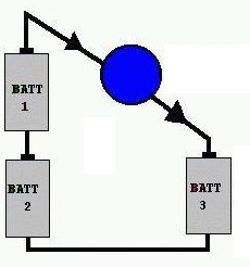
Let me explain the Split the Positive concept… If I were to ask someone – even someone with a background in electronics or electricity if a light bulb would light up if it were placed between the positives of the batteries as shown to the left, they would say no.
Let’s say they are 1.5 volt AA batteries. The two in series makes 3 volts and the other single battery is 1.5 volts by itself. Well, 3 volts – 1.5 volts in opposition means there is still a voltage potential difference of 1.5 volts between the positives. A LED bulb for example will indeed light up because potential differences are what are important in electricity and NOT polarity.
Here’s an important thing to understand – while the bulb is lit up, the current from the two batteries in series is charging up battery #3. Therefore, if battery #3 is dead, it will charge up as the bulb is lit. When it is charged, it can move to the position of #1 or #1 batteries and one of the batteries #1 or #2 can be placed into the #3 position and it will get charged up while the bulb is lit. So you can see that by constantly rotating these batteries, you actually wind up with way more load powering capability than you would get if you just ran the bulb on a single battery until it’s dead and do that for the other two batteries.
John Bedini came up with this method years ago after studying the concepts in the famous Ed Gray motor, which had a similar process, but with much higher voltages. The above example has been known as Bedini’s 3 Battery system and very few people have ever understood the profound implications of it.
Now when you combine this concept with a highly efficient Bedini Energizer where you can recover a high percentage of what goes into the system in addition to getting some extra electricity from some generator coils that have very low drag, you have the keys to be able to produce mechanical or electrical work while making up for virtually all its own losses. That means you have a simple system that keeps itself charged up and you can create the battery swapping part of the system with parts from your local hardware store!
Our power grid is doomed to crash and you will be at a very strong advantage with what RS is teaching you here in this presentation.
Part of the 2017 Energy Science & Technology Conference series (51 mins downloadable video).
Ronald Brandt was a brilliant experimenter who was successful in developing many Tesla and related technologies. He associated with many of the legends of the “Free Energy” and Tesla Sciences field including the late John Bedini who he shared his well-known “Tesla Switch” plans with that ran an electrical motor in a unique way that allowed the batteries to stay charged up while producing an abundance of mechanical work.
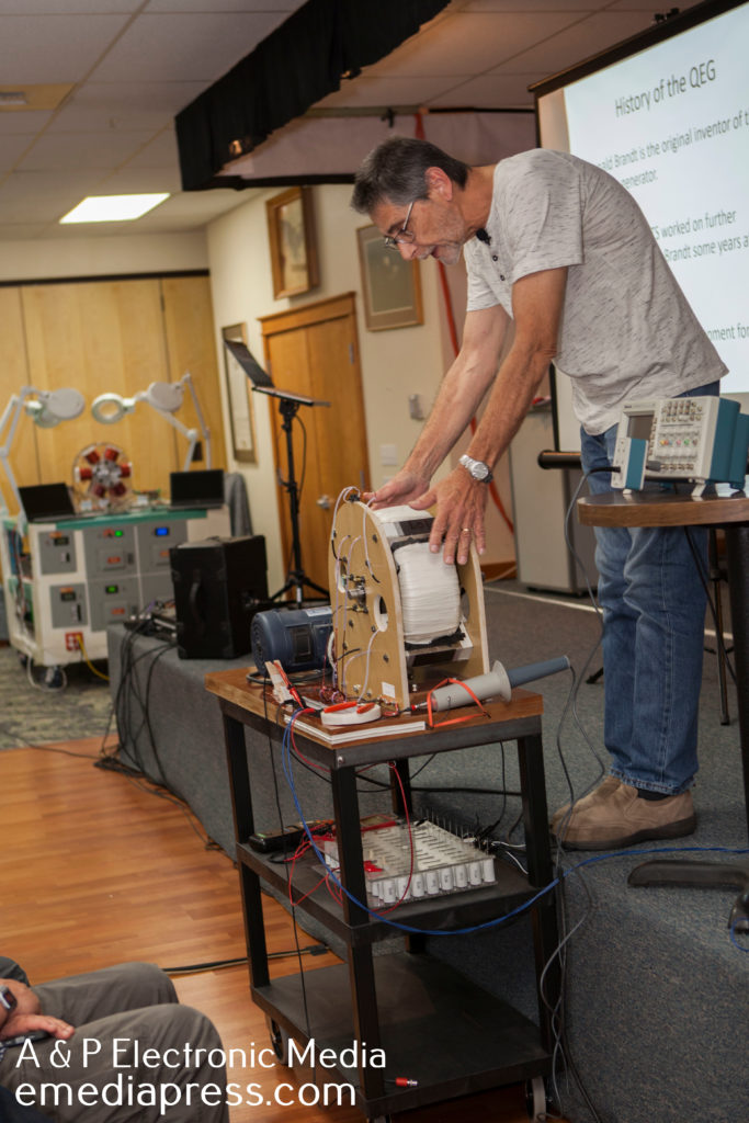
With a different methodology, he developed a generator technology that had high energy gains based on synchronizing various resonances in the system and this serves as the foundation for the Quantum Energy Generator or QEG project, which became an internationally known phenomena by Hope Girl and the Fix the World Organization.
The QEG is a switched/variable reluctance, variable frequency generator that uses mechanically pumped parametric resonance (tank circuit) to generate up to 30,000 volts of reactive power in its primary windings.
The reactive power in the core is then converted to real power by the secondary windings.
The QEG has 2 modes of operation; conventional mode, which produces about 800 Watts peak output for 1,000 Watts input, and resonance mode, where the machine is operated at a particular RPM/frequency to excite the fundamental mechanical resonant frequency (around 2.4 kHz) from a lower order harmonic.
In resonance mode the machine appears to be capable of overunity due to the output voltage increase afforded by the vibration of the core steel when the machine is driven into resonance.
Join us in exploring the possibilities by unifying all parts of the generator as one synchronized energy machine.
Also Included
Rare 22 minute video that includes the legendary Ronald Brandt discussing the generator that is the origin of the QEG
How to Build an Energy Efficient and Potentially Fuel-Less Generator – 254 page PDF
This is the QEG presentation you must have if you want to see in a very concise way what it is about, what the goal is and what is needed for it to achieve its ultimate objective.
Part of the 2017 Energy Science & Technology Conference series (84 mins downloadable video).
The Zero Force Motor concept has a long history dating back to the mid 1970’s and it has progressively evolved to its present day form as executed by Peter Lindemann in 2002 based upon John Bedini’s basic design parameters. However, Lindemann improved upon the basic design by building a 4 pole rotor versus the original 2 pole rotor design. The Lindemann ZFM (Zero Force Motor) was demonstrated at the 2016 Energy Science & Technology Conference with the basic design principles explained by Bedini and further detailed by Lindemann. The key here was the statement that the ZFM exhibited little or no BEMF.
The essential components of the ZFM are the use of opposing air core coils – no iron in the core – along with an internal 4 pole rotor sporting 4 neodymium magnets in a N-S-N-S configuration. This very unorthodox and out of the box design concept utilizes a Bi-Polar switching circuit for reversing the coil polarity every 90 degrees of rotation.
The 2016 ZFM demonstration clearly showed that this motor will operate at high speed with good torque, however no specific details were provided. This experimenter was clearly intrigued by the presentation and demonstration to the point where I harassed Peter Lindemann for more details and he clearly said “speak with John Bedini for more details”. Bedini listened to me for a few minutes and subsequently gave permission to photograph the demo ZFM and take any static measurements possible. Bedini gave permission to replicate the ZFM with his inimitable smile and his gravely chuckle with the parting words “listen to the machine, it will talk to you”, so began a most excellent adventure.
The ZFM build adventure was certainly an education filled with high hopes and many frustrations, ultimately resulting in a replication that screamed to over 13,000 RPM. The net result of this replication effort is the following video based on my Zero Force Motor presentation at the 2017 Energy Conference along with the companion E-book. This E-book details the history and theory of operation of the Zero Force Motor complete with John Bedini’s unpublished Lab Notes. Both the video and book describe specific design details.
With the above detailed information it is now possible to build this most intriguing motor and begin your own adventure into the unknown regions of the Zero Force Field. Who knows, you may discover and experience more mysteries within the Bedini Zero Force Motor.
WHAT YOU GET WITH ZERO FORCE MOTOR PART 1
115 minute downloadable video presentation by Yaro Stanchak
53 page PDF of the slides from the presentation
History of John Bedini’s journey with the Zero Force Motor Development
John Bedini’s Lab Notes that have never been released to the public
Many photos, drawings and schematics revealing all the details necessary to replicate it correctly
3 video demonstrations of different Zero Force Motors by John Bedini
Data charts and other details describing the personality and characteristics of the machine as well as some of the anomalous behavior that has been witnessed
88 page e-book with a compilation of John Bedini and Peter Lindemann’s personal comments about the Zero Force Motor. It also includes copies of the original lab notes relating to the Zero Force Motor, schematics and Peter’s ZFM design
Part of the 2017 Energy Science & Technology Conference series (115 mins downloadable video).
Hidden Dance – Zero Force Motor Part 2
Within this follow up presentation, you will find all the specs, which should be considered a standard built for more experiments to get start with. It works and has already been proven out by Yaro Stanchak and James McDonald.
Yaro also shares the differences in more detail on attractive vs repulsive mode and how this looks diagrammatically so the viewer can benefit from these findings. A thorough walk-through on the Zero Force Motor’s timing characteristics of the magnet’s geometry in relation to the coil geometry is covered. This is very important and cannot be stated enough – timing is crucial and can make or break your results.
Keep in mind this is a developmental process and there are no free energy claims. It is a novel motor with unique aspects that have not been used or exploited in conventional motors and bit by bit, the potential of what this machine is capable of is slowly revealing itself.
Pay close attention to the JZFM Excel data in the table presented by Yaro. You may find there is more than meets the eye. And you will definitely see that at certain RPMs, which may indicate some resonant points, that you will see the Hidden Dance happening within the machine as Yaro shows on the scope.
There is also a difference in the characteristics of how the motor operates in relation to its waveforms that are measurable if the ZFM is running on a battery compared to a linear current power supply. In other words, there appears to be advantages to running it on a battery compared to a power supply. Professor Robert Haralick during questions points out a very plausible reason for this and that is that when running, the ZFM is producing longitudinal waves that are accepted by the battery(s) but the linear amp power supply cannot.
This would be completely consistent with John Bedini’s experience over the years with experiments on the Bedini SG when running on and charging batteries, which have shown unusual input vs. output ratios and most of this disappears when running these machines on conventional power supplies. It has been stated over the years that the battery is very important as part of the open system and once again, these ZFM experiments shown by Yaro seem to indicate the same results.
WHAT YOU GET WITH HIDDEN DANCE – ZERO FORCE MOTOR PART 2
83 minute downloadable video presentation by Yaro Stanchak on the Zero Force Motor
49 page PDF of the slides from the presentation
Introduction and brief review of Zero Force Motor design and operation
This presentation covers the second self-recharging motor demonstrated at the conference and it is also based on some motor concepts developed by John Bedini along with some other concepts that came from others.
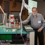
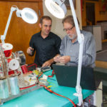
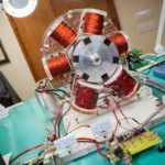
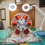
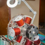
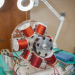
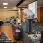
Mike starts off by covering the relationship with his partner Norman, where they came from and what led to the development of this Reactive Power Motor Generator.
He shows some of the pieces/components to the motor that were used in the context of how it evolved and how it started as just a motor when he first took it to Paul Babcock’s shop as well as the switching circuit that they needed to design to take it to the next level.
You’ll also hear how it ran for hours and at the end of the run, the input batteries were a few volts higher than when it started! So not only are the back batteries being charged, the front ones are too.
It’s also important to go up in voltage – this adds some complications for capturing the inductive spikes because the parts may not be rated for it, but there are many reason to go up in voltage. This even applies to the Bedini SG. Most people stick to 12v, but that is for learning. If you go up in voltage, then any voltage drops on the circuit wind up being a lower percentage of the total voltage compared to 12v. These concepts need to be considered and Mike and Norm incorporated these concepts into this machine.
Mike explains some of the challenges and methods they went through to deal with the higher voltages so they wouldn’t blow up so many parts.
It’s also important to understand a crucial aspect to the batteries that must be in place for both the front and back batteries to rise and its simpler than you might think.
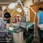
The importance of the air core is very important. Paul Babcock covered that in detail in his presentation and Mike will reiterate just how important this is. This machine will no perform like this if it has iron in its core!
When applying these principles, Mike winds up with a motor that runs COLD. The components don’t heat up. After it gets running, everything cools down on the switching circuit. And, that is with it outputting about 140-150VAC. Keep in mind that Mike’s goal is to power his entire home off of this machine.
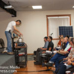
He runs the motor so you can see it in action and while it speeds up, he explains more of the nature of the machine and it ends with some Q & A where Mike shares more details and insights into this project.
It is important to understand this is not a “How To” and does not include the schematics. It is a story of Mike and Norm’s journey but he does share a lot of the concept incorporated into the machine that you can apply in your own experiments. To give you an idea of where to start, it is very similar to an air core Bedini SG running at a higher than normal voltage. Anyone that follows that path will learn a lot that they never experienced with iron core coils.
Mike does say after some of the IP is protected that he will share the how to so others can experiment with it.
Part of the 2019 Energy Science & Technology Conference series (84 mins downloadable video).
Here are some updates on the MWO – this is only for those of you who:
1. You already purchased one or more MWOs.
2. You’re on a waiting list and you may or may not have pre-paid for a system.
Progress working with fabrication companies to automate the various parts of the system is a very slow process but nevertheless, we are succeeding. The economy is so robust that 100% of every company we have dealt with is more busy than they ever have been.
They are doing their best to fit us in even though our needs are small compared to the monster jobs they’re doing for others. They also have been very forgiving with our persistent push-push-push and they do see a long term mutually beneficial relationship with us since there are quite a few other devices we wish to manufacture. We’re also fortunate all these companies are right here in Spokane.
Please take a look at what we have coming together compared to where we started not that long ago! We think you’ll like it…
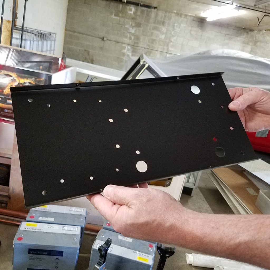
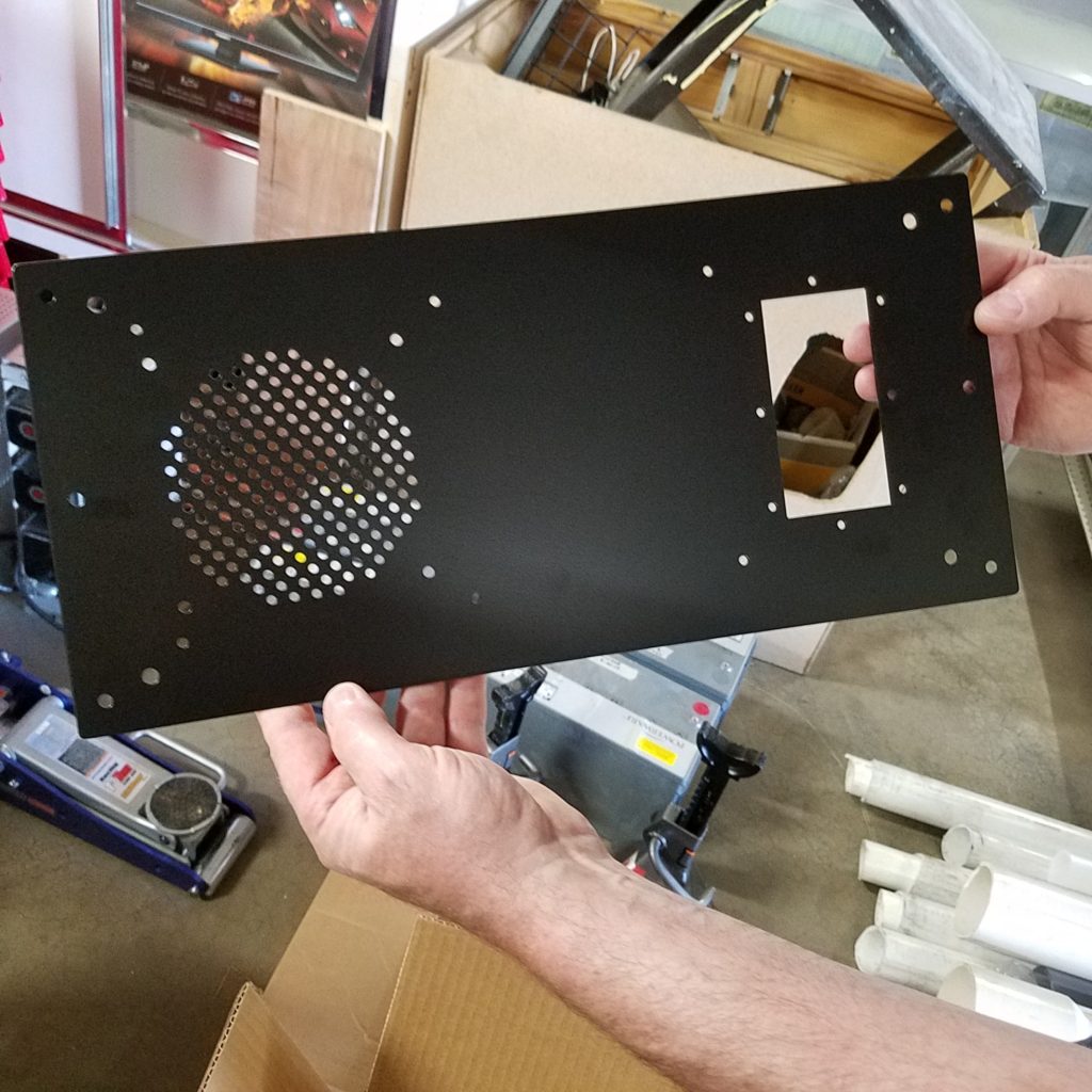
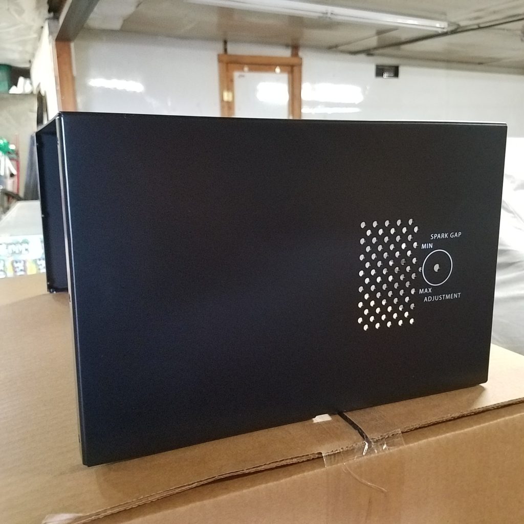
PULSE MODULATOR CASES
We have a local company that has created the cases for the pulse modulators and they’re beautiful! This was a huge step in moving towards turn-key production as the early units were all hand fabricated from scratch one at a time. We’ll be able to order these well ahead of time for future batches.
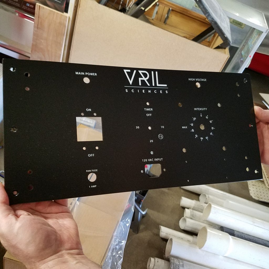
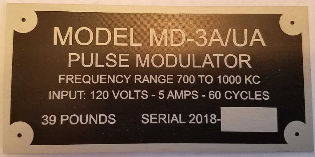
The picture below is the military style data tag that will go directly below the variac intensity dial – MD means Modulator, 3A is the prototype number and UA means invisible rays – this is the actual military designation for this kind of unit – and 39 pounds – the original prototype is about 55 pounds and the dimensions are larger!!
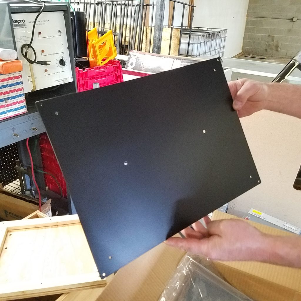
SPARK GAP BOXES, MOUNTING PLATES, COPPER BARS AND TUNGSTEN RODS
Not too exciting as far as pictures but suffice to say that we have all of this automated now and the copper and tungsten are now 1/4″ thick instead of 1/8″.
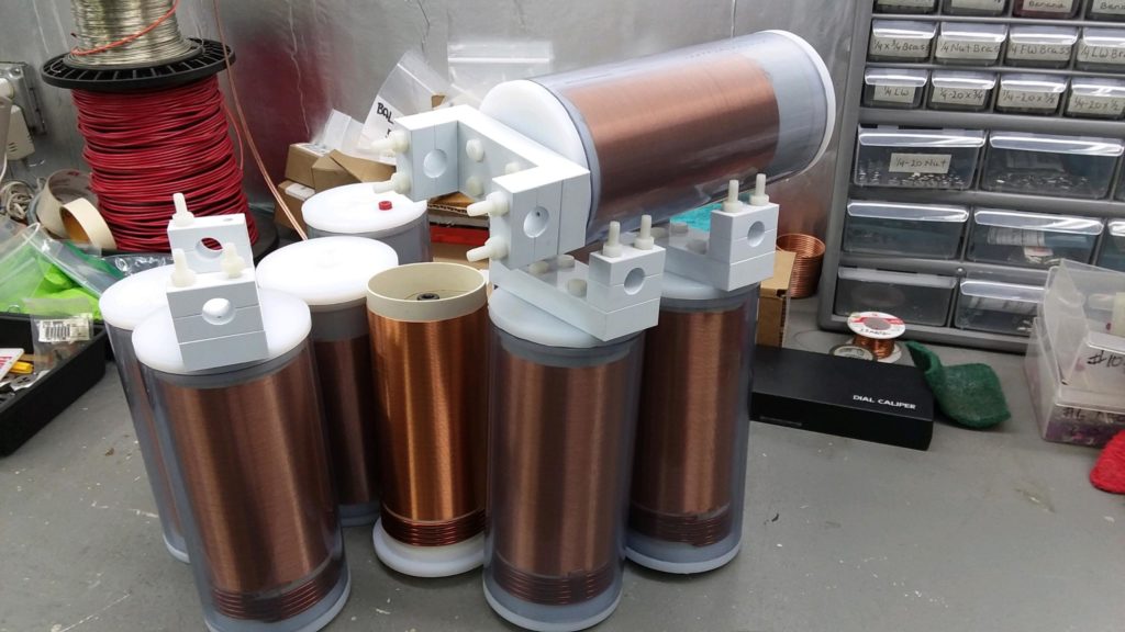
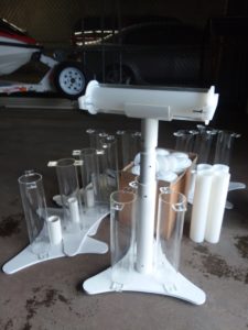
COILS & STANDS
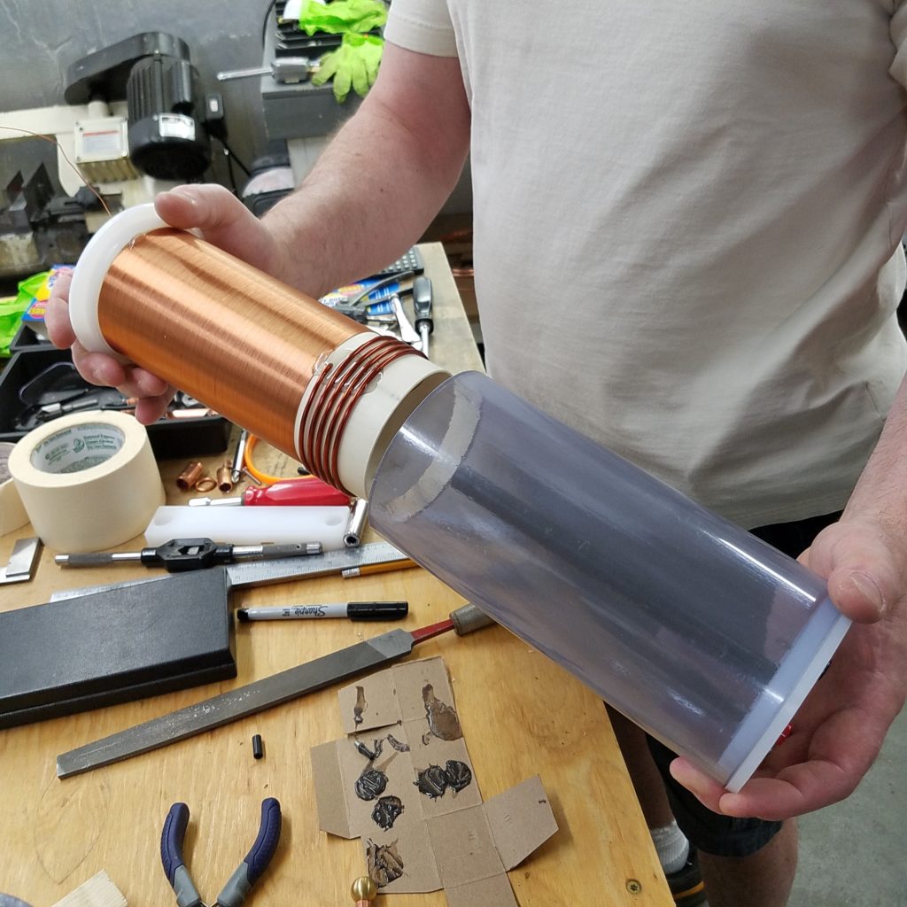
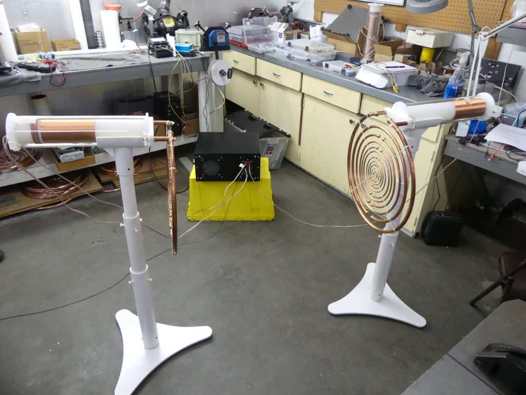
We have the stands design down that is much simpler and stronger to build and this will allow us to also go up in diameter for the coil forms eventually. A larger diameter with fewer turns to keep the same wire length gives us better frequency response – bottom line, they will perform much better and they will be more efficient.
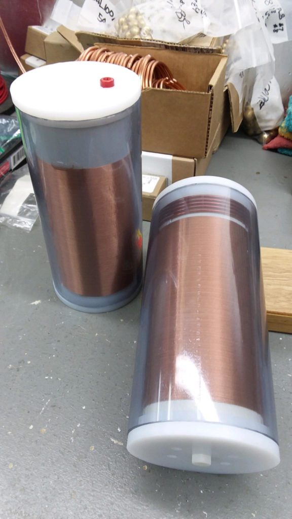
Also, the coil forms are much shorter. When the secondary is too far from the antenna, there are corona problems and we have solved this. You can see that the secondary (skinny wire) next to the right hand is butted up right against the end cap meaning it is as close to the antenna as possible. Since the antenna is like charged, corona will be subdued since it will not want to leave the end of the secondary and move out into space since the antenna repels it. This is using the antenna ring as a “gradient shield”, which is commonly used on high voltage power lines, but very rarely are these practices implemented on anything like this.
The original material for the clear tubes was acrylic but that was way too brittle. These clear tubes with the blue tint are ABS and are practically indestructible in this application. They’re also much more resistant to ozone.
The original units had 15,000 volt transformers and we quickly found that was too strong. We went down to 9,000 volt transformers and with the tuning improvements of the coil and a few other enhancements, we are finding that 9,000 volts is still too strong so if you receive a 9,000 volt unit, it is recommended to keep it around 50% max.
We are moving toward 6,000 volt transformers and this will let you use the full range of the variac without worrying about overpowering it even if you turn it up to 100%.
Overpowering doesn’t mean it will break the unit, but it does cause a lot of dielectric stress in the windings and can cause them to breakdown prematurely. This would be like having too much water pressure in a pipe that isn’t suited for that kind of pressure. With too high of voltage going into the primary (fat wire) on the coils, the dielectric stress is too much on the secondary windings and it isn’t good for the wire, plastic, etc. and is simply not necessary. This is really a subtle energy machine even though the pulse modulator is not very subtle.
The stands will look pretty much like the ones in the pictures below. You can see how the secondary (skinny wire) is a few inches from the antennas and the newer ones are butted right up against the antenna.
The original ones were probably 4+ inches from the antennas and there was too much corona. Anyone that has the older coils will receive replacements at no extra cost when we are caught up. For most people, it will take a long time before any issues arise. For anyone running these for many hours a day, that will speed up the issues but again, for most people running these once or twice a day, it will take a few years:
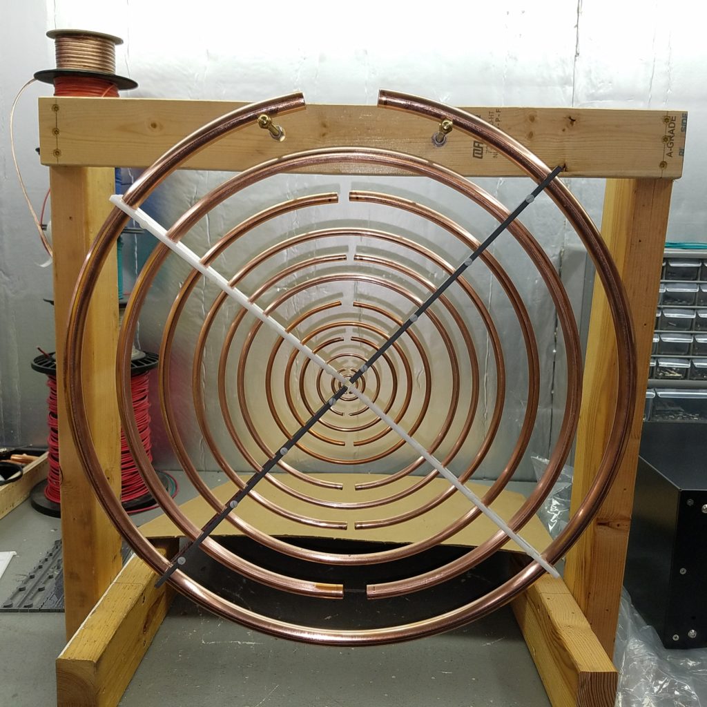
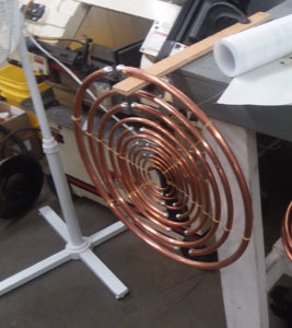
ANTENNAS
It is obvious why hardly anyone is building these on their own. The antennas are a whole project on their own and unless someone has all the tooling, it will take them forever to build a unit. The lacing with the silk string is the #1 most time consuming process especially getting to the inner rings. There is no advantage to this silk and sticking with a method that is 75 years old is not useful, helpful or necessary. It looks nice, but there are too many drawbacks.
We have a company that will be automating the ring bending process for us and this is going to save a massive amount of time. Also, instead of lacing the strings, we’re going to be using some plastic strips that clamp the rings together. The plastic is gray and is not the most beautiful, but it is CPVC, which is a special PVC only available in gray and is very resistant to ozone – one of the best materials for this purpose.
We calculated this all out with Eric Dollard and since the total thickness of this material on all 4 quadrants is less than 1% of the total circumference, there will be no significant change in the frequency response. In other words, going this route will enable us to keep the same high performance.
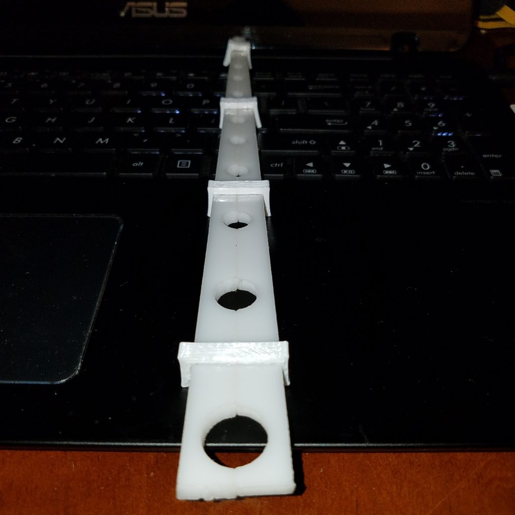
Check it out – looks really good!! The rings are more stable and do not move or swing in relation to each other like they do with the silk and they are able to be assembled in a fraction of the time.
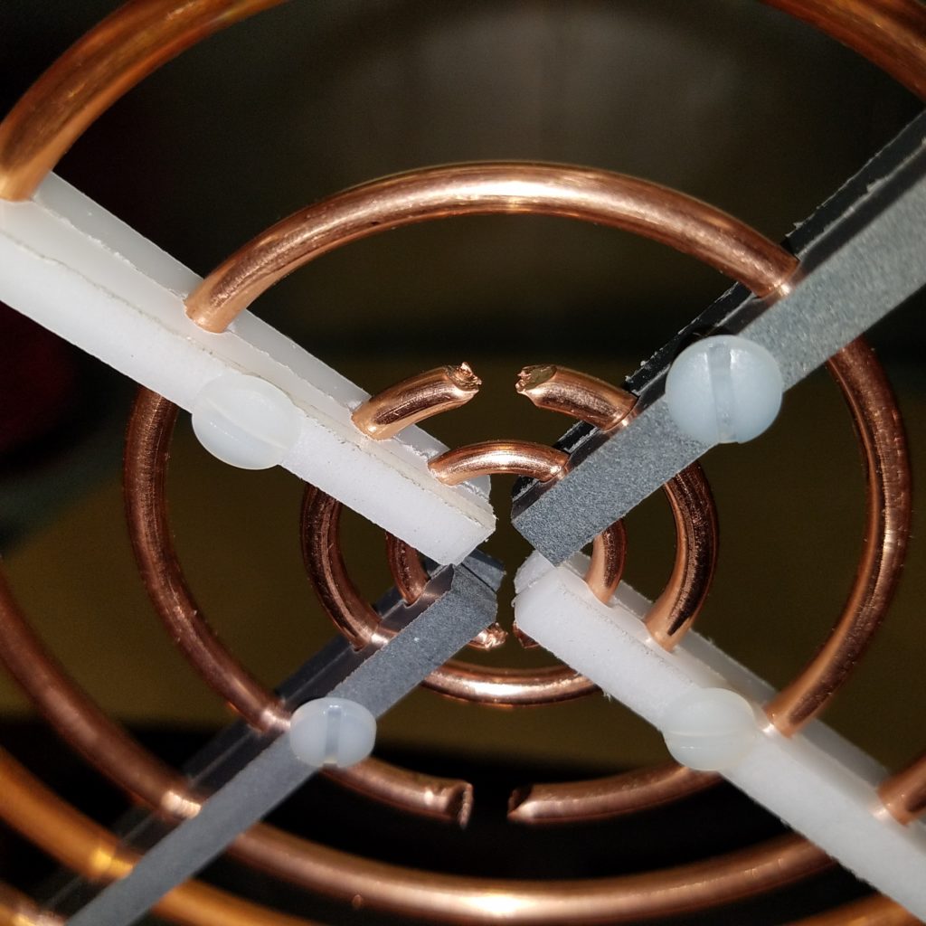
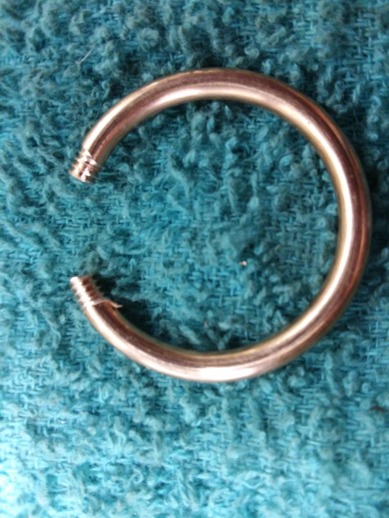
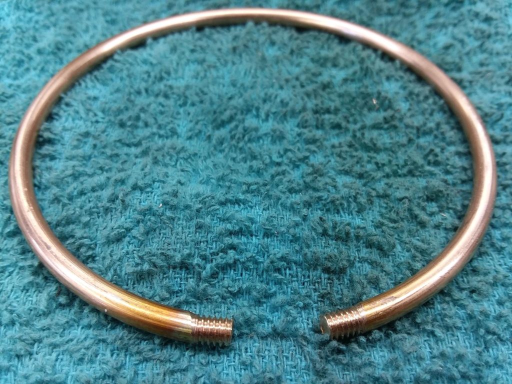
The rings are without balls and the ends the tubes are not cut to fit the balls yet, this is just to test the test strips we had cut for us to make sure they are perfect, and they are.
What you see are two colors of strips. The white is UHWM, which is one of the best dielectric materials, but it is not that ozone resistant. So we’re going with the gray CPVC and are having these cut out for us by the hundreds.
Below, you can see that this works great all the way down to the center rings!
So that is the progress that we’ve made and it has been an interesting, complicated and rewarding challenge.
TIMELINE
Our timeline – we have 6 units in the current batch that are long overdue. We apologize for the delay, but you will have a MWO system that is far superior than what we thought we were going to offer. We hope to have these all out by the middle of next month. I’m personally spending as much time at Jeff’s shop as I can to work on these to speed it up as much as we can. The entire month of July was spent getting the fabrication company squared up on how we need the antenna rings bent and solving the strips to clamp down the rings.
There are 6 units in the batch after that, which we’ll start on at the end of September or Beginning of October and we plan to be able to ship those all out by the end of November. With so many parts being automated for us now, this kind of timeline is looking more realistic.
After that, there are about 6 people on the waiting list for the batch after that, which will be started at the end of November or beginning of December. We will start to accept payments for those Mid October so we can order anything needed for them and have those in our hands when we’re ready to start.
Around this time, we will have more of the system in automated production and will be looking for a local company that can start the assembly for us – probably the same company that does the Bedini RPX units 100% turnkey for us. It will then become an order fulfillment and testing process for us and we won’t have to build any of it ideally and we definitely won’t have to fabricate anything. When that happens, we will start production on some new devices that we will share at a later time. In any case, anything we manufacture after the MWO is something we can probably do blindfolded in comparison and we’re really looking forward to that!
Thank you all for your patience and support and we’ll post any new updates here.
Sincerely, Aaron Murakami
MWO UPDATE 2018-10-27
Greetings everyone,
A lot of progress has been made – it has taken a while, but considering the massive amount of work, it has been very worthwhile to have taken this much time.
Here’s the latest…
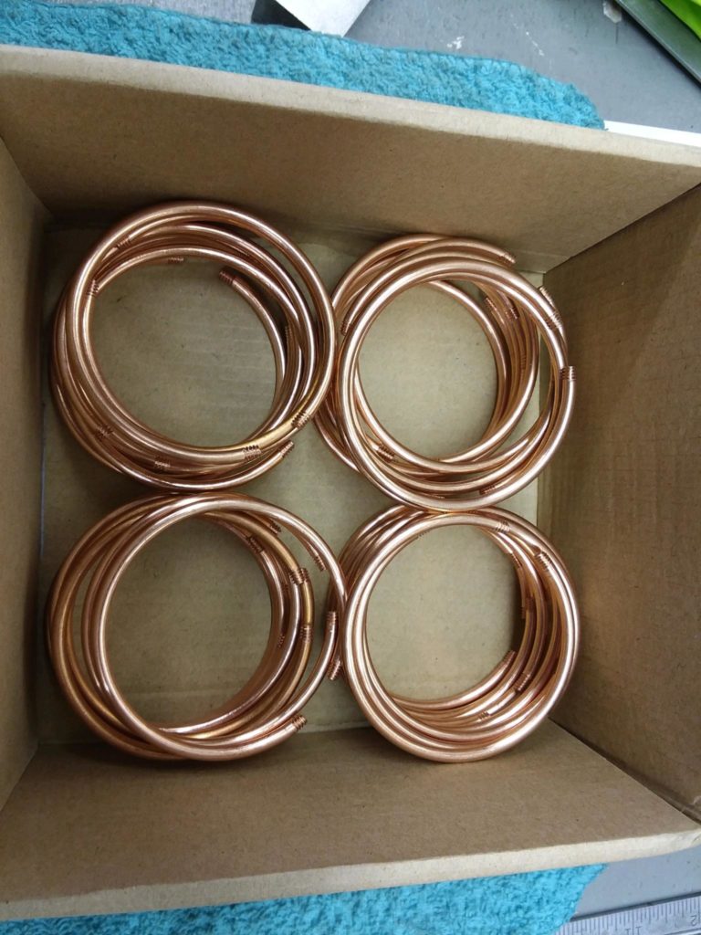
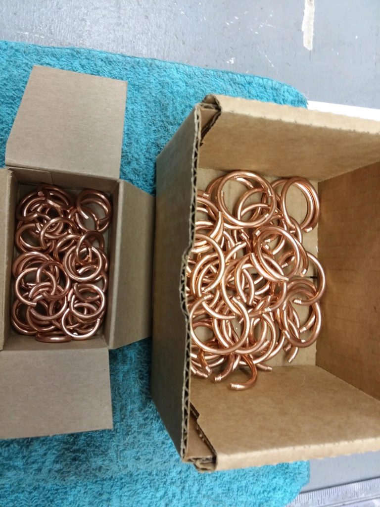
We have a local company bending the antenna rings for us and this is the #1 most complicated part of the project to get into automated production. There are very few companies in the entire United States that are even willing to take it on let alone who can even do it to begin with and thankfully, the only one in the entire Northwest USA happens to be right here in Spokane.
For now, they’re doing rings 1 (largest outside one) through 8 and Jeff is doing rings 9 through 12 (the smallest inside ones). We’re having enough done for 20 entire MWO systems and not just the 6 that are currently pending.
We opted to take the route of long term feasibility, which took longer verses the short term satisfaction of getting a handful of units out a bit quicker. We believe in the project wholeheartedly so invested quite a bit into this aspect of the project. In the near future, they will also be bending the smaller rings for us as well. All future batches will be simpler and quicker. By spring, we anticipate that future orders in good numbers can be fulfilled in 10 weeks or less.
If you’re in the batch of these first 6 units, I deeply apologize for the delay, but we’re definitely not slacking around – we’re all in full bore and working nonstop.
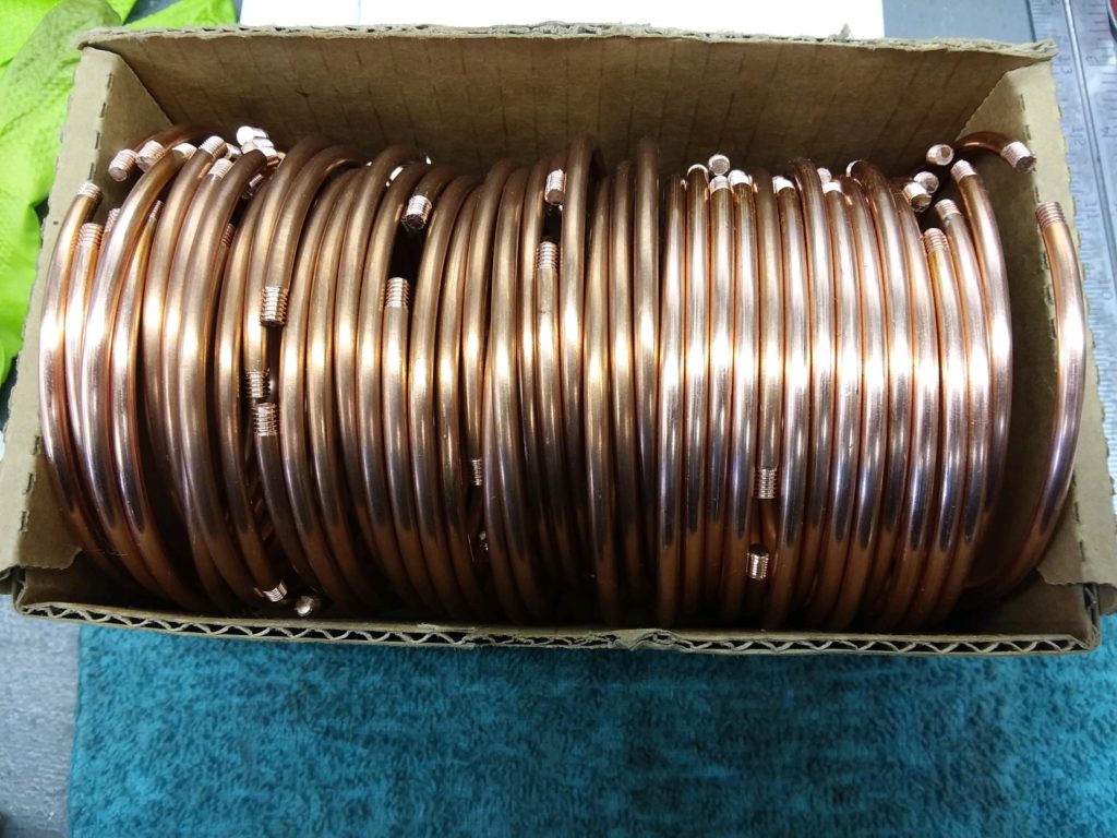
October 25th, a couple days ago, is when all rings were supposed to be powder coated with a clear coat, but some of the tooling wasn’t right that they received and it’s being redone right now. Also, the form that the rings are going to be laid down into in order to confirm the rings are proper was not perfect and that is being redone as well.
This isn’t holding up all the other progress. Jeff has all the smaller rings done and are ready to hand them over to be powder coated with the rest of the rings right when they’re done.
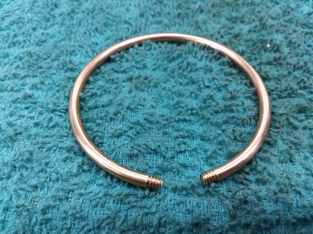
These rings looks simple, but making the diameters precise, polishing them and threading the ends for the brass balls is extremely time consuming. This is for this round (there are enough for 20 systems worth of antennas) and the company bending the larger rings for us will take on the smaller rings after the 20 current systems. Of course these are all done manually one by one at this time, but they will be done for us next time.
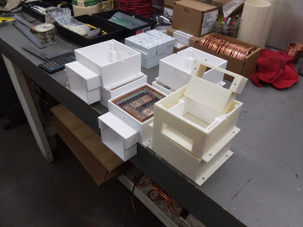
We’ve perfected the dimensions of the spark gap boxes and air ducts, which are 3D printed. The cases are produced for us and each one is exact so one design will work perfectly on all. This was a challenge to get them just right, but we finally got it. The tolerance for the dimensions are within 0.01″, which is pretty tight for something like this.
In the last major update, we showed you the plastic strips that are to hold the rings together. The original plan was to tap and thread them so a nylon screw could hold them together. This was a massive effort and will never be practical.
We are now going to have slots (clips are in the slots, which can’t be seen) in the strips for clips to be 3D printed that will hold the strips together. The design works, we just have to work out the perfect dimensions. The rings will force the gap between the strips apart just a bit so the clips have to be designed to accommodate for that. We will adjust for that once the rings are done. We will be able to perfect those fairly quickly since it only takes a few modifications to the CAD design of the clips, we’ll select the perfect material for the clips to be printed in, etc. Here are two pics to show the idea.
To give you an idea of how valuable this clip idea is – it took 5 days full time to lace 1 set of antennas – that is two antennas for a single MWO system. 5 days!
With these strips and clips, we have taken a 5 day job and reduced it to a 1 hour job or less!!! That is about how long it will take to lay the rings in a form, center them and clip the strips on.
Now that the spark gap boxes and air ducts are done for all 6 pending units, in a couple days, I’m heading to the shop to help Jeff assemble the pulse modulators while he is working on the coils and stands. We should be able to complete all of this fairly quickly. As soon as the antenna rings are done, hopefully in a couple weeks or less, then we’ll have everything needed to complete the 6 units.
In the last major update shown up above, it says, “There are 6 units in the batch after that, which we’ll start on at the end of September or Beginning of October and we plan to be able to ship those all out by the end of November. With so many parts being automated for us now, this kind of timeline is looking more realistic.”
So far, it looks like we’re not too far off. Originally, I thought we were going to be able to get one at a time done and ready to ship, but since it looks like we’ll have everything done except the antennas and they’ll all be done at once, we’ll probably be shipping all 6 units within a couple days apart. So far, I’m still confident that all 6 units will be ready to ship before the end of November. That is contingent on if we get the antenna rings in our possession soon enough.
After that, the next batch of 6-7 units should be all ready to ship by the end of the year or mid January at the latest.
DECEMBER 19, 2018 UPDATE
Here is the latest update and possible final one before we start shipping units!
Below is a picture of all the coils for the current 6 unit batch.
These are only 8-10 inches long, which is all that is necessary. The skinny wires are the secondary windings, which are closer to the end so they are going to be extremely close to the antenna. The antenna will have the same high voltage charge as the wire going to the antenna so the antenna will act as a “gradient shield”. What this does is help suppress the high voltage corona around the wires in the tube, which will extend the life of the wires.
It is common for many high voltage Tesla type coils to have their magnet wire oxidize and turn dark, but some steps can be taken to reduce this. It normally does not affect the operation of the coils so it isn’t a big deal if they turn dark – my own coils are slightly darkened – but we do want to mitigate the possibility to the fullest extent. Also, there is Super Corona Dope, which is the best paint on high voltage protective coating and some thick layers are brushed on to the secondaries to help suppress the corona as well. This will be the first batch of coils that have secondary windings that close to the antennas plus the Super Corona Dope coating applied to the wires. These coils will also be more efficient because any reduction in corona is an increase in output to the antennas!
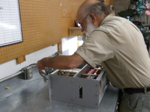
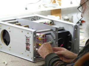
I’m at Jeff’s machine shop daily right now building the Pulse Modulator units. That is the black case that holds all the electronic components that causes the high voltage output to the MWO antennas.
Here is our timeline – please note that I’m posting your FIRST AND LAST INITIAL next to the timelines so you know when you can expect your MWO system to be delivered to the shipping company. When we take it to the shipping depot, we will put you in touch with them so you can pay for custom-boxed, motor freight shipping with a credit or debit card over the phone. Again, the average price around the country is about $550. It could be a bit more or less depending on distance.
We still have to automate about 25% of the production for these units and then we will look at having a local company do the assembly for us. When this is accomplished, hopefully by Summer of 2019, we can handle almost any quantity and have them ready in 8 weeks or less.
Thank you to all of you who have been very patient with us while we worked out the manufacturing automation for the MWO systems. There are been countless updates and upgrades to the MWO system, most are invisible, but you are definitely getting a MWO system that is far superior to what we could have offered if we put expediency ahead of quality. Our goal is to create these systems to last so they will be worthy of Heirloom status. We will continue to simplify the manufacturing process while increasing the quality at the same time. The last 14 months has been very challenging and rewarding for all of us!
Once the MWO systems are a bit more automated, we will work on other products (there is nothing we could build that is as complex as the MWO – so it is all downhill from here!!!) Projects that need the machine shop are like Bedini motor kits and related.
A few projects that I’m working on right now, which I’m able to develop at my home lab:
LIGHT THERAPY CONTROLLER – There is a red/infrared light controller that will be a part of a universal system. It will use the same battery and signal generator that comes with the RPX Sideband Generator combo kits available at http://sidebandgenerator.com. I have 20 years experience with pulse LED therapy devices and worked with some of the pioneers in this industry before 95% of the current manufacturers were ever involved. The goal is to provide various peripheral devices that can be plugged into the master control unit. This may be hand held devices, pads, face masks and so on. Anyone that already has an RPX combo will already have a battery and signal generator that will work. The prototypes already work perfect and I expect to make these available by Spring or sooner. Since there is infrared, I can make GRAS claims without FDA approval. GRAS = Generally Recognized As Safe. That includes, relaxation of tight muscles, improved circulation, temporarily relieve pain and a few other claims. Energy balancing claims are also permitted. There are many other benefits that I may delve into but at a more appropriate time. There is a Wellness category of claims and I’m looking into how it applies to these devices. In 1981, an aerospace engineer created the first LED device for healing and it was for a famous horse doctor. A medical doctor (Charles T. McGee, M.D.) and qigong master Roger Q. Estes) I worked with in the late 90’s and early 2000’s were close associates with that engineer and horse doctor so my experience with these devices and what works and what doesn’t work goes right back to the very pioneers who invented the LED therapy device modality to begin with. I believe my experience can provide a valuable contribution to world of LED healing devices.
RPX SIDEBAND GENERATOR LINEAR AMPLIFIER – The Bedini RPX Sideband Generator’s output is around 1.5 watts and is extremely effective because of the pump wave. That is a low frequency square wave that the high frequency sideband Rife Frequencies piggy back on. That allows deep penetration and is the only valid way an electrode based Rife machine can possibly work. Otherwise, the high frequencies are simply trickle over the skin (skin effect) and don’t get to where they want to go. The reports of effectiveness with the stock unit is mind blowing and you learned some of this at the last conference if you went and that will not be released to the public. I can’t make claims but others are free to share their stories. We have gotten many requests for an amplifier and I have replicated Bedini’s amplifier that was included in a higher power unit he built for me, which has around 10-12 watts output. That is roughly 6-8 times more powerful. The problem with all current RPX units is that the pump wave cannot get through the amplifier when it is amplifying the high frequencies. It was thought that an amp would be useless for all the RPX units that have been sold for the last three years, which has the pump wave and high frequencies tied together on the output. I know what John Bedini’s thought process on this was because we talked about it and I studied his linear amplifier designs for the RPX. I appear to have discovered something that went unnoticed – I now have prototype amps that all RPX units can be plugged in to that allows the pump wave to exist on the output and they work perfect! The efficiency of my amps are about 30% above Bedini’s for the same input and same design. The amps I built might be a bit too powerful so after Paul Babcock can help me with some final verification of the power readings, I’ll choose what power level will be in the final design that goes to production.
S5A12 – 5 amp 12 volt solar charge controller. With the right solar panel capability and enough light, these charge controllers will push the batteries where they need to go in order to bring them to a proper topping charge, which is different from conventional belief. This gives the batteries a theoretical infinite life cycle span because on each charge cycle, the chemistry is revered to like-new. John Bedini only built one S5A12, which I tested thoroughly on a local school campout where I volunteered to teach simple solar energy classes. The S3A12 was the most popular one we offered when John was still building them and we never had a chance to put the S5A12s into production. The prototypes I made replicate John’s results perfectly and I also built them with surface mount components as well. That means I will never have a production problem with them. For nearly 10 years, Peter Lindemann and I were in a chronic 3 month back order situation (literally for almost 10 years straight) because we sold all of John’s chargers way faster than his company could build them. They were worth the wait, but with surface mount components, I can easily have hundreds of units in my hands in 4-6 weeks flat. The same local company that manufacturers the RPX units for me will be building these. I expect to release the S5A12 by spring as well. I will be working on the final designs for a 20 amp 12 volt system after the S5A12.
There are other projects in the works, but the above 3 have prototypes that have been extensively tested. By the end of 2019, I expect to have 10-12 products into full bore production. That’s the latest update – if you have any questions, please reply the email that had the link that brought you here.
Happy Holidays and have a Happy New Year!
Aaron Murakami
Your initials will be posted below if you have pre-paid for a MWO machine – each first and last initial is unique so if you pre-paid and you see your initials, they are your initials and there is no possibility that the initials are for someone else. The order that the units will be ready are in order that the payments were received:
TARGET DATE TO DELIVER YOUR MWO TO THE SHIPPING DEPOT:
20 UNITS ARE AVAILABLE FOR PURCHASE – CONSTRUCTION WILL BEGIN AT THE END OF JULY, 2019 AND 4 PER MONTH WILL BE COMPLETED. THE FAST YOUR ORDER, THE EARLIER YOU WILL RECEIVE YOUR UNIT.
PRIORITY AVAILABILITY WILL BE OFFERED TO ATTENDEES OF THE 2019 ENERGY SCIENCE & TECHNOLOGY CONFERENCE.
We are in the process of building a dedicated website for the Lakhovsky MWOs. Paul Babcock gave a presentation on this at the 2017 Energy Science & Technology Conference here: http://emediapress.com/paulbabcock/universalmedium/
The Lakhovsky MWO remained a mystery until about 10 years ago because nobody actually knew what circuit he was using. Some originals were found crated up and they were reverse engineered and turned out to be quite different from Lakhovsky’s patent drawings.
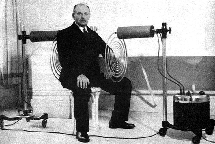
Lakhovsky Multiwave Oscillator (MWO)
This is one of the most desired high frequency and high voltage machines ever created and only a few companies are manufacturing them according to Lakhovsky’s actual design.
In Europe, purchasing a correctly built one will cost you $25,000 USD by the time you receive it here in the states – it’s very expensive because it’s a replica of the early 1900’s units for those that want the old look.
The only company in the United States making them charges almost $4000 but it is built in a wooden box so it is not shielded so there is a massive amount of interference that can mess up your routers, computers, etc. Our associate has one and found it was not wired properly so he had to modify it to work right. Plus, it will take you 3-4 months or longer to receive it.
All the “MWOs” that uses plasma tubes, ignition coils and other nonsense are all phony MWOs, period.
You can also use this unit to power Tesla Coils for regular experimentation, you can use this unit as the pulse modulator if you want to replicate Eric Dollard’s Cosmic Induction Generator invention, etc. This unit is truly UNIVERSAL and we are the only ones that are offering this! You are getting a Ferarri for the price of a Subaru.
Here is a bit about the unit we are making available in limited quantities at this time:
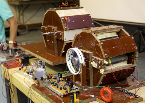
Eric Dollard working on and designing the MWO’s Pulse Modulator
Eric Dollard, the man considered to be THE modern living Tesla since he is the only one to have replicated Tesla’s true wireless electricity system and finished all the mathematics to make it engineerable, has personally designed the MWO’s Pulse Modulator (the unit that produces the high frequency and high voltage impulses that gets sent to the antenna rings).
NOTE: A PORTION OF THE PROCEEDS WILL BE DONATED TO EPD LABORATORIES, INC. A 501(C)3 NON PROFIT ORGANIZATION TO SUPPORT THE WORK OF ERIC DOLLARD.
Eric Dollard designing the Pulse Modulator for the MWO
If the US Navy, Bell Labs and Western Electric combined their talents to build a Lakhovsky MWO, then this is what you would wind up with – a compact, highly shielded, low loss and high power output unit that is practically military spec. There is no comparison anywhere in the world, not even close.
Lakhovsky Multiwave Oscillator (MWO) antenna standsThe stands are high quality design meant for stability, long life, plus they look AMAZING! READ THIS CAREFULLY – The difference in the units we are offering you is that there will not be a see-through outer tube because they’re too fragile. The picture is showing a museum piece, but for long life and strength, it will be white or black plastic, which enables us to strengthen it’s coupling to saddle it is resting on. The end caps will also be white or black plastic (different material than shown) for extra strength.
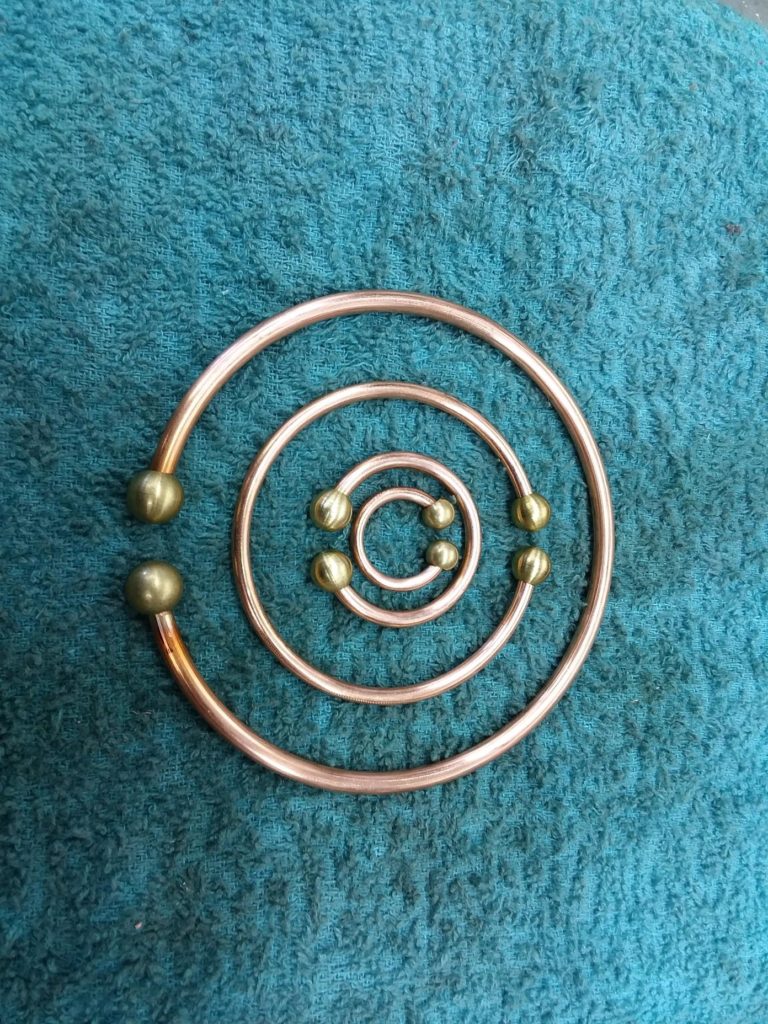
MWO Antenna
The antennas are precisely measured to spec and are also very beautiful! They are laced together with silk, which does not stretch ensuring that the rings are always the same distance from each other. Lakhovsky had several ring variations and we chose to model this one after one of the most popular variations.
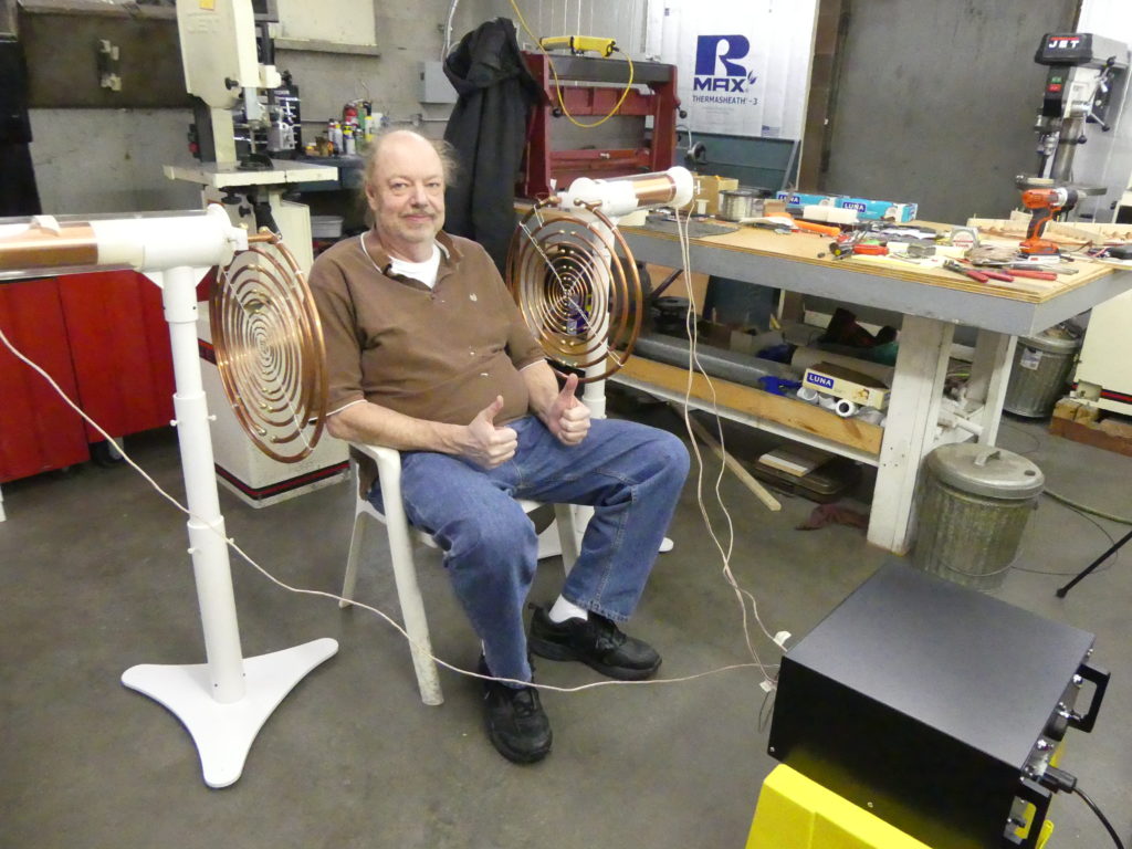
Eric Dollard & Paul Babcock
Paul Babcock is also on the team of consultants who has assisted in the testing procedure and we have verified that the waveform that our MWO units produce is 100% identical to Georges Lakhovsky! He was the first one of our associates to build a MWO from scratch based on the real circuit used by Georges Lakhovsky.
Paul got us on the right track, Eric showed up and the rest is history. We will continue to make refinements as needed and we are honored to be able to offer this * RARE * machine that was made possible by these two engineers who have inspired and helped us with their genius.
Peter Lindemann has contributed to the design of the stands so that they look good and are also very functional. Peter has been an advocate of Georges Lakhovsky MWO technology before most people have ever heard about it.
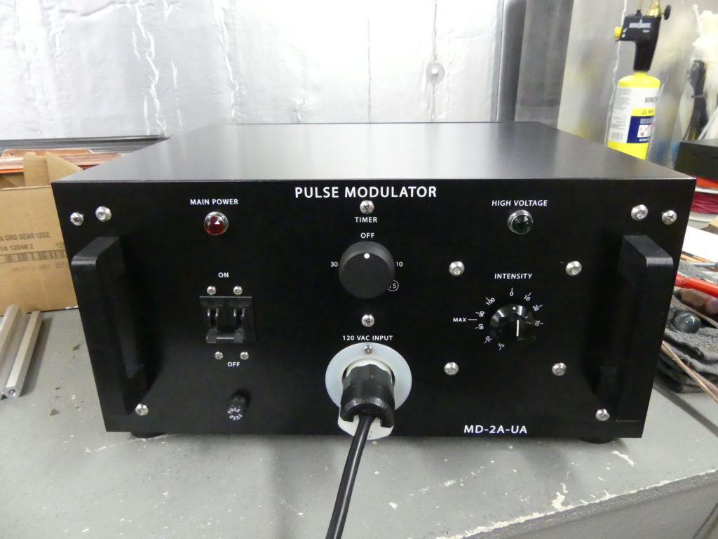
MWO Pulse Modulator
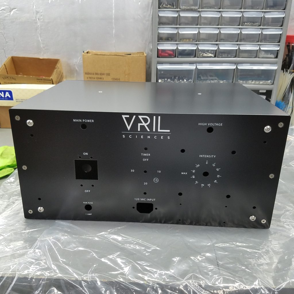
Instead of our units looking like something from the early 1900’s, it looks like a modern analog military radio design in a small compact package and it is 100% electrically identical to the Lakhovsky MWO. There is no need for it to come in a case 5 times this size. The Pulse Modulator in the picture above is what we have created.
The units we are offering you will also NOT have a twist lock plug connection front center as it is not needed, it will have a common trapezoid shaped computer or monitor power supply plug. The left switch is a magnetic-hydraulic circuit breaker that turns on the main power, top center is a dial for the timer and the dial on the right is the VARIAC (Variable AC) dial. The cases are powder coated (the best kind of painting/finishing method) and silk-screened with white labeling on the front for all dials, etc. along with the name and model of the unit.
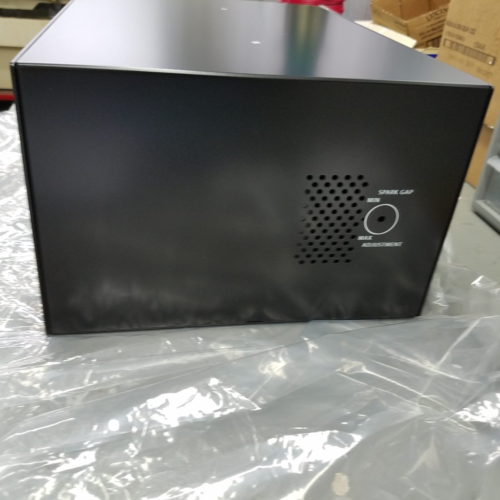
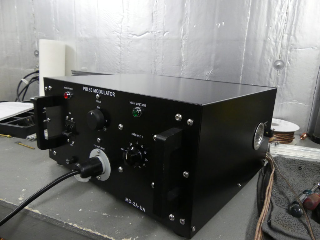
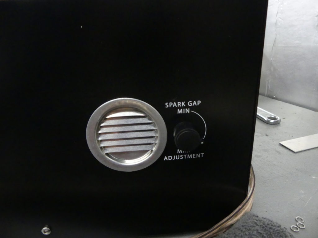
You can see on the right side is the spark gap vent and dial to adjust the spark gap.
The dial is to adjust the spark gap, we recommend keeping it a bit on the minimum side and leave it. Just because your sports car can go 200 MPH doesn’t mean it needs to.
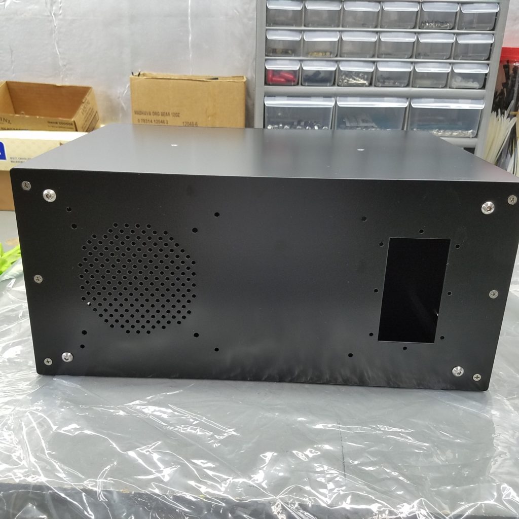
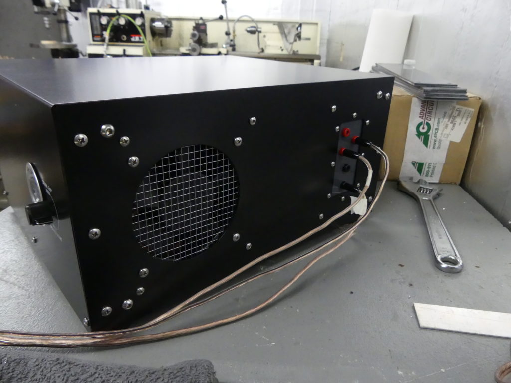
The left side shows the fan guard for the spark gap and the right side are where the coils/antennas plug in to.
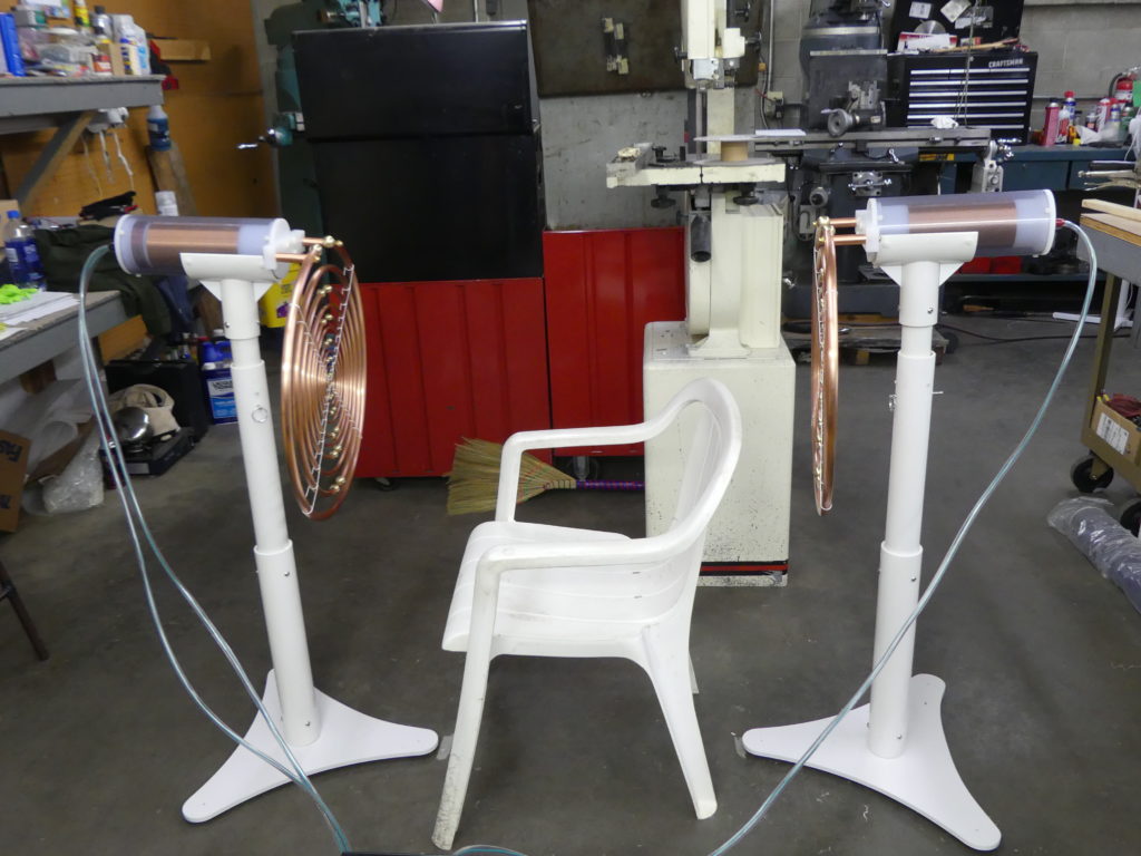
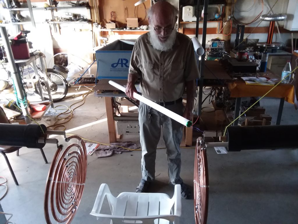
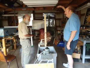
Here is what the full system looks like with both antenna/coil stands plugged in.
Here is Paul Babcock enjoying the ride! For normal use, the chair would be pointed the other way so the legs are not close to the wires, but we are just testing things out. He’s giving the thumbs up because not only is our waveform perfect, the primary and secondary coils are perfectly tuned! In other words, the primary tank circuit (primary input coil, capacitors and spark gap) are in resonance with the secondary (output) coils.
It’s about time someone brought this technology into the modern age and there is nobody more qualified than this team of engineers!
If you want to learn more about the MWO, get Paul Babcock’s presentation and read Georges Lakhovsky’s Secret of Life book that you can download as a free PDF here: http://www.fundebien.org.mx/pdf/THE_SECRET_LAKHOVSKY.pdf (we cannot endorse the publisher or person who wrote the introduction) – we only recommend reading what Georges Lakhovsky wrote himself.
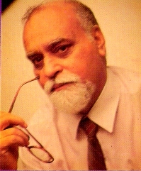
Paramahamsa Tewari, author, inventor, and retired Executive Director (Nuclear Projects) of the Nuclear Power Corporation of India (NPCIL), passed away on November 27, 2017, in his hometown region close to Varanasi, Uttar Pradesh. Mr. Tewari, who was 80, is survived by his wife, Venodini Tewari, and three children, Arvind Tewari, Sarala Paliwal, and Anupam Tewari. A B.Sc. Engineering graduate from Benares Hindu University, he had a career over four decades with NPCIL. His pioneering contributions, however, extend beyond his professional career. He is the author of a revolutionary theory in physics, the Space Vortex Theory (SVT), and a number of books on the same, that won early commendation by Nobel Laureates in physics. His theory led him to invent the Tewari Reactionless Generator (T-RLG), a high-efficiency electrical generator.
Paramahamsa Tewari was a life-force that burned bright with innate curiosity about the physical and spiritual worlds, deep conviction in the power of creativity, and an entrepreneurial spirit and approach to problem-solving. He was committed to the broad uplhiftment of society, particularly the underprivileged, and meaningful employment for talent. Animal cruelty prevention was a cause dear to his beliefs. With people, he was personable and interested in their individuality. Somewhat of a raconteur, he enjoyed recounting anecdotal stories from everyday life. Nature was a source of inspiration for him. Building a boat by hand with a friend, a love of sports, driving through the Himalayas multiple times in his less-than-powerful Standard Herald sedan, were each fueled by his adventuresome spirit.
Please join his family for a memorial, open to the public, to honour his memory, on December 9, 2017 at Venodini Nivas, P.O. Gotegali – 581317, Karwar, Karnataka, India.
Paramahamsa Tewari
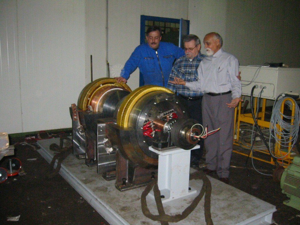
The generator technology the Tewari was involved with is a “reactionless” or drag free generator, which means it does not produce a counter torque against the prime mover turning it when electricity is drawn from it and his machines have been measured to produce around 250% more electricity than is supplied to the prime mover.
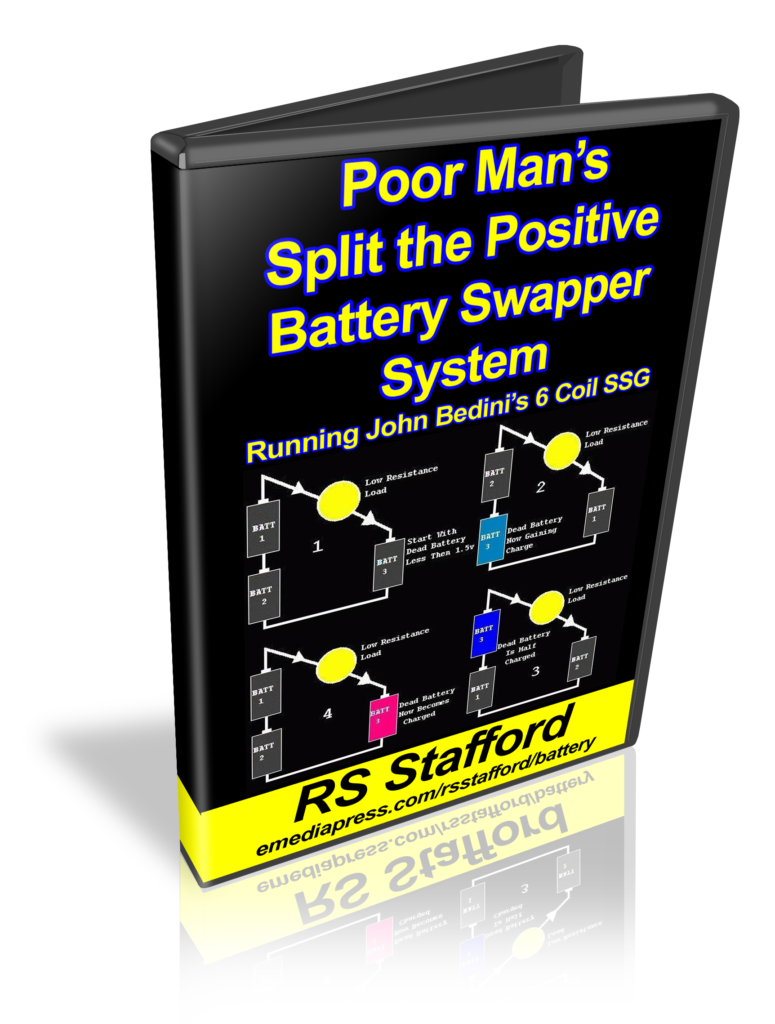
Poor Man’s Split the Positive Battery Swapper by RS Stafford
At last year’s conference, Peter Lindemann demonstrated a Bedini SSG energizer that produced a lot of mechanical work all weekend and the batteries stayed charged up!
It worked beautifully and was done with an automated circuit that rotates the batteries in a certain way but most people do not have the know-how to be able to build that circuit.
At this year’s conference, RS Stafford replicated this battery swapping method with circuit breaks and other common parts from his local hardware store. It’s inexpensive and very, very simple to build. This is the machine that ANYONE can make work if they just follow some simple wiring diagrams and RS’s instructions.
Let me explain the Split the Positive concept… lf I were to ask someone – even someone with a background in electronics or electricity if a light bulb would light up if it were placed between the positives of the batteries as shown to the left, they would say no.
Let’s say they are 1.5 volt AA batteries. The two in series makes 3 volts and the other single battery is 1.5 volts by itself. Well, 3 volts – 1.5 volts in opposition means there is still a voltage potential difference of 1.5 volts between the positives. A LED bulb for example will indeed light up because potential differences are what are important in electricity and NOT polarity.
Here’s an important thing to understand – while the bulb is lit up, the current from the two batteries in series is charging up battery #3. Therefore, if battery #3 is dead, it will charge up as the bulb is lit. When it is charged, it can move to the position of #1 or #1 batteries and one of the batteries #1 or #2 can be placed into the #3 position and it will get charged up while the bulb is lit. So you can see that by constantly rotating these batteries, you actually wind up with way more load powering capability than you would get if you just ran the bulb on a single battery until it’s dead and do that for the other two batteries.
John Bedini came up with this method years ago after studying the concepts in the famous Ed Gray motor, which had a similar process, but with much higher voltages. The above example has been known as Bedini’s 3 Battery system and very few people have ever understood the profound implications of it.
Now when you combine this concept with a highly efficient Bedini Energizer where you can recover a high percentage of what goes into the system in addition to getting some extra electricity from some generator coils that have very low drag, you have the keys to be able to produce mechanical or electrical work while making up for virtually all its own losses. That means you have a simple system that keeps itself charged up and you can create the battery swapping part of the system with parts from your local hardware store!
Our power grid is doomed to crash and you will be at a very strong advantage with what RS is teaching you here in this presentation.
Ronald Brandt was a brilliant experimenter who was successful in developing many Tesla and related technologies. He associated with many of the legends of the “Free Energy” and Tesla Sciences field including the late John Bedini who he shared his well-known “Tesla Switch” plans with that ran an electrical motor in a unique way that allowed the batteries to stay charged up while producing an abundance of mechanical work.
With a different methodology, he developed a generator technology that had high energy gains based on synchronizing various resonances in the system and this serves as the foundation for the Quantum Energy Generator or QEG project, which became an internationally known phenomena by Hope Girl and the Fix the World Organization.
The QEG is a switched/variable reluctance, variable frequency generator that uses mechanically pumped parametric resonance (tank circuit) to generate up to 30,000 volts of reactive power in its primary windings.
The reactive power in the core is then converted to real power by the secondary windings.
The QEG has 2 modes of operation; conventional mode, which produces about 800 Watts peak output for 1,000 Watts input, and resonance mode, where the machine is operated at a particular RPM/frequency to excite the fundamental mechanical resonant frequency (around 2.4kHz) from a lower order harmonic.
In resonance mode the machine appears to be capable of overunity due to the output voltage increase afforded by the vibration of the core steel when the machine is driven into resonance.
Join us in exploring the possibilities by unifying all parts of the generator as one synchronized energy machine.
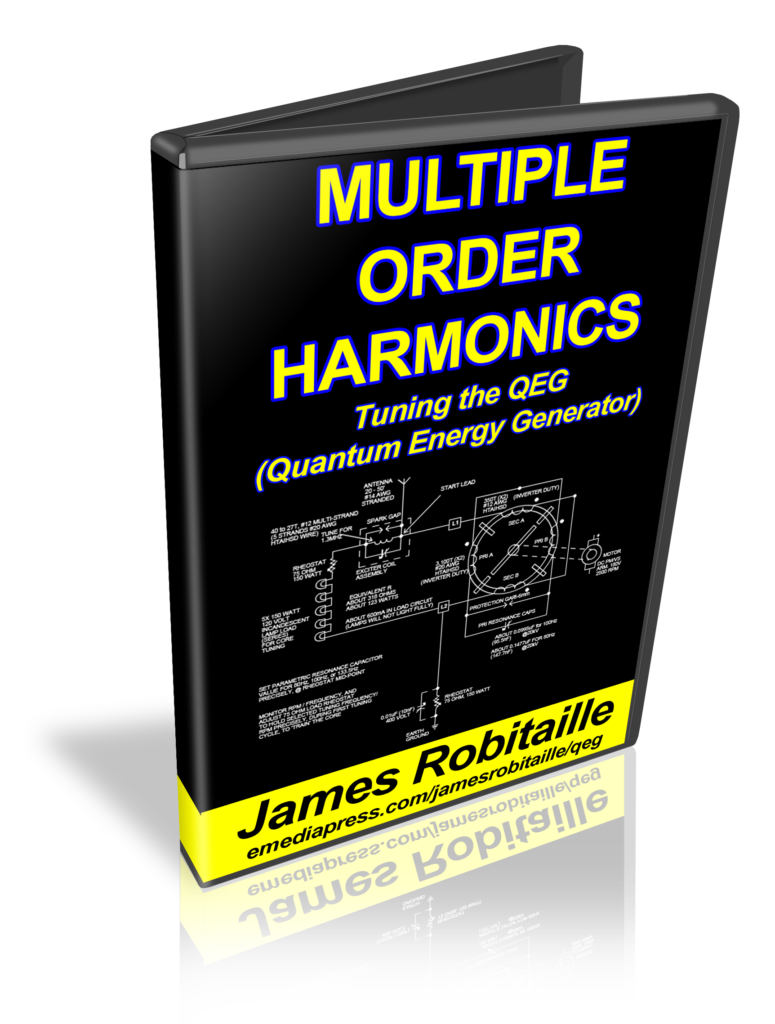
Multiple Order Harmonics – Tuning the QEG by James Robitaille


 Let me explain the Split the Positive concept… lf I were to ask someone – even someone with a background in electronics or electricity if a light bulb would light up if it were placed between the positives of the batteries as shown to the left, they would say no.