Veljko’s 2-stage oscillator is an amazing device that produces more mechanical work than it takes to run the device. It’s in use by hundreds of companies around the world pumping water, grinding grain, etc.
Veljko Milkovic’s mechanical amplifier known as a 2-Stage Mechanical Oscillator is one of the simplest true overunity machines that most people can build. Using some very clever innovations in pendulum mechanics, it allows gravitational potential to contribute to real mechanical work.
At the 2015 Energy Science & Technology Conference, Veljko Milkovic’s team was kind enough to provide a video presentation, which is a compilation of much of his work relating to this machine as well as other pendulum concepts.
This machine is not theoretical – it works and is being used not just as an experimental device, but as a water pump in low income areas. It allows more water pumping work to be done than the operator has to input into the pendulum themselves. Again, demonstrating simply that gravity is a source of energy contrary to the mainstream belief.
Wait until you see the demonstration in the video with the flashlights!
The Veljko Milkovic Research & Development Center has produced a couple books highlighting some of their research in these areas.
The first is called Basic Principles of Overunity Electromagnetic Machines by by Jovan Marjanovic, M.Sc.
The goal of this book is to unlock the secrets of over unity and to teach people what is over unity and how it works. The reader will learn basic ideas of making new ultra efficient electric motors and generators and how to improve existing patents which use permanent magnets.
The second books relating to gravity power is Gravitational Machines by Veljko Milkovic.
This is the story of the discoveries, which have been hidden from us for a long time, and were dismissed as science-fiction, until nowadays when breakthrough inventions are receiving awards, appraisals and objective criticism, but also dogmatic a priori attacks.
Perhaps it is time to change the perspective since new ideas and materials brought about breakthroughs in gravitational machines which are fully functional and can be used for various purposes.
The aim of this book is to present as many facts as possible, which will lead us to the light at the end of the tunnel.
Conventional physics is in alignment with Newton’s 3rd Law of Motion where every action is supposed to have an equal and opposite reaction. However, that is a misunderstanding of natural phenomena because the reality is that the combined forces are divided between two reference points and that is a huge difference in the interpretation of nature. However that may be, this still does not permit a propulsion system with no reaction at all.
An important distinction is that there actually are mechanical systems, which take a reaction but turn it around to help push the machine/device/system in the forward direction. That means that the reaction is not opposing anything and is actually used to become additive to the original forward motion that created it to begin with. That means more forward work is accomplished compared to the work that was input and this violates no laws of physics contrary to conventional belief. Take note that there still is a reaction, but it does not buck the forward intended motion.
Now, lets get to systems that have no apparent reaction whatsoever. We’re not talking about using reactive power to do forward work, we’re taking about a system that appears to have no reaction at all.
Recently in the news, a new space propulsion drive is being admitted by NASA to have no reaction and it is ruffling some feather. An astrophysicist told Space.com, “The reason it’s controversial is, it violates Newton’s Third Law.”
EmDrive
The concept was invented by Roger Shawyer who calls it an EmDrive. Microwaves are bounced around inside a conical shaped container and without any propellant, a small amount of thrust is created. This has been verified by researchers at NASA’s Johnson Space Center in Houston.
The thrust produced is extremely small but nevertheless, it works and of course needs to be researched and developed further. It is always a good sign when we see conventionally trained academics and engineers admitting that something is doing the “impossible” and is apparently violating the coveted laws of physics.
It seems that the conical shape is causing a simple potential difference between the narrow and wide end giving it somewhat of an asymmetrical dipole effect that appears to be related to a century old discovery.
A reaction-less space drive has was invented and proven out in the 1920s – almost 100 years ago!
Thomas Townsend Brown developed an interesting propulsion system using capacitors charged to a high voltage. When charged up, the capacitor moves through space in the direction of the positive terminal. Here is a short excerpt from his British Patent #300,311, A Method of & an Apparatus or Machine for Producing Force or Motion:
“The invention also relates to machines or apparatus requiring electrical energy that control or influence the gravitational field or the energy of gravitation; also to machines or apparatus requiring electrical energy that exhibit a linear force or motion which is believed to be independent of all frames of reference save that which is at rest relative to the universe taken as a whole, and said linear force or motion is furthermore believed to have no equal and opposite reaction that can be observed by any method commonly known and accepted by the physical science to date. ”
This reaction-less propulsion system from he 1920s is not just theoretical, it demonstrates what is known as the Biefeld-Brown Effect, which is the basis for a field known as “Electrogravitics.”
Ten years ago when I first wrote The Quantum Key, my layman’s Aetheric Unified Model predicted the proper direction of movement in this manner without having ever heard of the Bifeld-Brown Effect. Basically, the positive charge of the aetheric source potential is repelled by the high voltage positive at the leading edge of the “craft” and this causes it to be deflected over the shell towards the negative end. Simultaneously, the implied anti or negative charge of the aether pulls on the positive end of the craft and causes it to move along at a negative resistance and this seems to be the obvious reason for no reaction – there simply is no positive resistance it is moving in to. Since the positive aetheric source charge is what causes inertia by imparting an electrostatic repulsion against the protons that make up the mass, inertia is reduced since that which causes it is no longer moving through the atomic matrix of the mass that makes up the craft – it is deflected over it. This appears to be the main principle at play in any asymmetrical thruster that has no reaction.
Anyway, the mainstream sources of information are really mainstream sources of disinformation because it is constantly claimed that the effect is nothing more than ion wind and that the movement is ion propulsion, but it is not. There is a small bit of ion wind, but not even close to being enough to account for the amount of lift or thrust given to an apparatus utilizing the Biefeld-Brown Effect.
The most common is known as a “Lifter” and you can see a very basic one in operation here:
Here is a PDF of a report from the U.S. Army Laboratory stating, “The calculations indicate that ionic wind is at least three orders of magnitude too small to explain the magnitude of the observed force on the capacitor.” Force on an Asymmetric Capacitor
We’ve been extremely busy since before the conference, during the conference and are still running non-stop since it was over. The conference presentation videos are all edited and will be made available about one every 5-7 days or so.
These presentations are listed in the order that they were given at the 2015 Energy Science & Technology Conference.
Dr. Douglas Lindstrom spoke on the ECE Unified Field Theory – and amazingly, much was quite understandable to the layman. He did cover some mathematics but also covered many concepts involving overunity processes in cold fusion and even parametric oscillators, which are going to become more and more popular in this field. There are references to some of the parametric work and some has been replicated and verified. His presentation will also include a PDF of the powerpoint with all the notes. Dr. Lindstrom works with Dr. Myron Evans – Tom Bearden considers him the most important physicist alive.
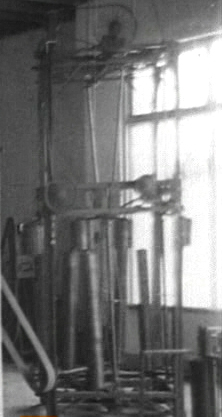
Al Throckmorton‘s presentation was very inspirational. This was a very rare appearance. Half of his presentation was really his story about who is he and much of his life experience, which was filled with priceless nuggets of wisdom. He had his special water gas pump, which is detonated with the plasma ignition circuit. We couldn’t pump water with it since we were in doors, but he did fill up the chamber and detonated the gas and the pressure gauge was over 200 psi, which is way more than enough to pump a very substantial amount of water. We’ll be including some diagrams and schematics for the pump so others see exactly what it is. The first application will be for small village use in Africa to pump water over long distances to improve the quality of their lives, which much of it is spent simply carrying water miles and miles from a remove water well.
Aaron Murakami (I) presented on the plasma ignition. Last year I spoke about the theory, operation, etc… with some demos. This year’s talk was to specifically show how I overcame the issue of wasted spark ignition systems and how to put the plasma ignition on these ignitions, which are so common these days.
Paul Babcock presented on Ethanol, debunked a lot of the anti-ethanol propaganda that is so popular and showed some of the designs that he and his brother have developed, which make small scale ethanol production a breeze. Ethanol is freedom and you’ll really learn why in this presentation. Ethanol is as good as cash or even better if you have a smart game plan and in these financially troublesome times, this information is priceless.
John Bedini showed his self-running motor – it was the first thing he showed me 16 years ago when we first met. It is really 3 machines in one and operates on one set of old 25+ year D cell alkaline batteries that are corroded, the springs in the battery holder are rusted out and the batteries are just taped in there. He spins the rotor and it starts off slow, turns a rotor with a propeller and blinks LEDs to show what phase the motor is in. By the end of John’s talk, it is about 25-50% faster than it was in the beginning – not because it took that long to get to full speed but because it recharged its own running battery over the course of the presentation.
Graham Gunderson showed a simple transformer setup and demonstrated that it not only makes up its own losses, but actually produces a bit more. The overunity is small, but it is something he wanted to share with everyone because if you can’t get to unity, you’re not going to get to overunity. Since there is an obvious lack of enough replications of several overunity devices that many people are attempting, taking baby steps with this very simple transformer concept is absolutely necessary. Any builder with basic technical skills can make this transformer and by following Graham’s instructions and references, they can achieve the same results.
William Lyne gave a fascinating comparison between some of the propulsion ideas of Tesla and J.J. Thomson. Eric Dollard was the one that actually suggested this topic since there are many gems inside of Occult Ether Physics by William Lyne. J.J. Thomson is one of the most important scientists to understanding not just the electrical sciences, but the real physics of the aether.
Paul Babcock‘s second presentation was on Magnetic Energy Secrets part 3 where he makes it VERY simple to understand what is necessary to create an overunity motor. He breaks it down to 3 very simple principles that almost anyone can understand. Paul covers multiple machines that have overunity results and shows how they are all adhering to these concepts. Back EMF is the bane of overunity and he shares the principles necessary to create a motor that does not generate – meaning there is simply no back emf!
Jim Murray presentation is crucial to the successful replication of his Dynaflux Alternator. Many who have tried to replicate it have failed. He shared the most important secret to understand to making it work as well as disclosing for the first time ever several pieces of information that were never disclosed in the patent. The patent has been expired for a long time now so it is public domain and he wants everyone to be able to understand what it is really about. The COP is over 2.5 on his laboratory bench model, which means it produces over 250% more electricity than it takes to run it.
Jeane Manning moderated this year’s Panel Discussion, which included Eric Dollard, Al Throckmorton, Graham Gunderson, myself (Aaron), Jim Murray, Paul Babcock, William Lyne and Douglas Lindstrom. We discuss some common threads between different valid overunity technologies, the creative process and its importance, Graham and Eric discuss Tesla’s patent which utilizes Cosmic Rays to charge capacitors to power loads and Eric gives some very clear specifics on this as he has replicated this in the past. There are multiple discussions about splitting water without electrolysis using electrostatics to rip the water apart without running current through it. Al Throckmorton’s water fuel cell for the pump that he demonstrated does not use electrolysis to split the water, it is a water capacitor and it works incredibly well. I share one patent on this kind of process that I tried to duplicate in the past and Eric Dollard discusses his friend’s work in this area who successfully mastered the electrostatic separation of water. Before we started the Panel Discussion, we gave recognition to the four Electrical Engineering students and two musicians who won the contests to have their conference and lodging costs covered by an Anonymous Donor.
Veljko Milkovic was not at the conference but his team was kind enough to provide us with a video compilation of quite a bit of his work. We played some of this during some of the breaks but did not have time to show the whole thing. Veljko Milkovic is the inventor of the popular 2-Stage Mechanical Oscillator, which produces many times more mechanical work that it takes to run the machine. This will be posted on YouTube at some point so everyone can watch it and learn more about his work.
Stephen P. McGreevy gave a very interesting talk on natural VLF radio recording. The Earth and atmosphere is constantly creating all kinds of music and other sounds, which are not audible to the human ear. Animals hear these sounds building up before an earthquake and that is how they know an earthquake is about to strike so they flee the area. Even if there is no natural disaster coming, these sounds are constantly around us. Stephen shows us many of the places where he traveled to record these sounds, he demonstrates the difference between the sounds and how different places sound different, various antenna methods to pick them up the best and anyone can get the receivers through his website so you can experience this as well. This is a fun and simple way, especially for children, to get in touch with the world around them. There are also schematics to build your own receiver that are open sourced on his site. This talk is highly related to Eric Dollard’s Advanced Seismic Warning System.
John Polakowski did not make it to the conference so to replace his presentation, Graham Gundreson gave a one hour presentation and John Bedini followed up with a one hour presentation.
Graham Gunderson went into a lot of detail on his experience with Floyd Sweet’s VTA (Vacuum Triode Amplifier) technology. Graham, John Bedini and one other individual has more experience experimenting with the VTA than probably everyone else combined. Graham spent 10-15 years on this nearly full time. The VTA used special barium ferrite magnets and the information that Graham shared about their special properties is rarely known by anyone in the “free energy” community. He discusses how they can be programmed to oscillate at very specific frequencies. Many of the REAL principles involved with the VTA are shared and Graham also shares about someone’s work who replicated the VTA type concept using some Bedini SG circuits and barium ferrite magnets to charge the batteries in his electric car. This presentation is priceless and is a must have for anyone that ever wanted to know what the VTA was really about. You’ll also learn quite a bit about permanent magnets in general that is not widely known.
John Bedini surprisied us again by demonstrating his Gravity Tuner circuit that measures activity in our spacial environment as well as demonstrating his famous Kromrey G-Field Generator. This was a shocking demonstration for most everyone at the conference because as it ran, the magnets turned cold instead of hot and when he lit bulbs with the output, it sped up. Also, shorting the output made the G-Field generator speed up and it demonstrated the pure white sparks, which are a phenomena of true negative energy circuits.
Eric P. Dollard finished the conference with a presentation that lasted almost 4 hours. If anyone can take multiple seemingly unrelated topics and tie them together with such mastery, it is Eric Dollard. He goes into the fact that J.J. Thompson is the key person when it comes to understanding the real aether physics, morphic fields and golden ratio archetypes all around us, concepts of levitation and musical harmonics and how the waveforms can tie together to give huge impulses that can catapult physical objects, science based on natural principles and how modern times has entered a new dark age with the current models that only serve to maintain ignorance about such principles and what direction we need to go to move back in the right direction. Eric goes into depth about Pythagorean mathematics and how it is key to understanding the natural science that is hidden in this day and age as well as much in depth discussion on various musical scales using the real Pythagorean ratios, which were accompanied with a few audio samples that were put together by Seattle Music Composer Charles Roland Berry. This allowed everyone to hear the difference between the ancient musical scales and today’s common scales. Eric even covers a fair amount about Gustav LeBon and covers many comparisons showing the mirror images between some of the music of Bach and polyphase power systems with many examples using his Versor Algebra diagrams. Needless to say, anyone that does not understand the relationship between music and electricity after watching this presentation has not been paying attention. In the end, Eric summarizes this presentation with an in depth discussion of the physics of the aether based on the work of J. J. Thomson including the mathematical equations of the aether that nobody else has been able to figure out because J. J. Thomson convoluted so much of it in his own writings because he never kept a continuity between different mathematical variables so it has always been confusing. If anyone can straighten out this mess, it is Eric Dollard and that is exactly what he has done so for the first time ever, you will be able to see as clearly as possible based on what is in J. J. Thomson’s work what he was really after. This presentation is THE definitive lecture on J. J. Thomson and the true physics of the aether.
That is a total of 15 videos from the 2015 Energy Science & Technology Conference. Vejlko Milkovic’s is not an actual conference presentation and that will be offered for free on YouTube later. Both of John Bedini’s presentations will be offered at some point through Energetic Productions and the other 12 videos will be offered by us through A & P Electronic Media.
The release schedule so far is as follows with the rest of the schedule coming soon:
August 3, Monday – Paul Babcock, Magnetic Energy Secrets Part 3
August 9, Sunday – Jim Murray, The Dynaflux Concept & Lenz’s Law
August 15, Saturday – Eric Dollard, The Power of the Aether as Related to Music and Electricity
August 18, Tuesday – Jeane Manning, Panel Discussion – FREE VIDEO
August 19, Wednesday – Eric Dollard, Versor Algebra Volume 2 – Special Theories of Sequence Operators as Applied to Power Engineering This is not a conference presentation – it is the second release of Eric Dollard’s Versor Algebra book series.
August 25, Tuesday – Aaron Murakami, Plasma Ignition For Wasted Spark Ignition Engines
August 30, Sunday – Al Throckmorton, The Lord’s Pump Project (HHO Water Pump)
September 4, Friday – Graham Gunderson, BOTH of Graham’s presentations will be released simultaneously on the simple overunity transformer and on the VTA.
September 9, Wednesday – Douglas Lindstrom, ECE Unified Field Theory
September 14, Monday – Stephen P. McGreevy, On the Art of Natural VLF Radio Field Recording
September 19, Saturday, William Lyne, On the Parallel Propulsion Researches of Tesla and J. J. Thomson
September 24, Thursday, Paul Babcock, Ethanol is Freedom
Here are some various comments I made about this Skinner Machine:
Sun, Earth, Moon
The relationship of the upper weight to the lower weight shaft is like the MOON and EARTH. The Earth rotates on its own axis while the Moon does not. However, as the Earth moves through space once around its axis of rotation around the SUN (lever), the moon has made one rotation. In a year is a day and the Earth goes around the Sun one time per day, the Moon has spun 360 degrees in that one day while all the time showing it’s same side to the Earth.
If you took a string with a weight on the end, held it out and turned in a circle, the string would stretch out and the weight would go out and be held by the string. As you turned around in circles on your own axis, the same side of the weight is facing you so to you it is not rotatig on its own axis, however, with each one rotation you make on your own axis, the weight (moon) has indeed revolved 360 degrees in space.
I don’t want to get too much into all of that right now, but something to think about. The whole Skinner mechanism is like the Sun, Earth and Moon where it takes one day for the Earth to revolve around the Sun and the Moon always stays in the same position relative to the Earth and Sun like the 3 points of a right angle triangle and the hypotenuse is from the Sun to Moon and the right angle is at the Earth..
Not a perfect analogy but the principles are all there.
The first force in the Skinner machine is the electric motor, which is mechanical work to turn pulleys by belts to move the mechanism that rotates the input lever in an elliptical motion. The whole machine has multiple levels of leveraging leverage so to speak.
That motor doesn’t need to supply very much work to turn the top of the lever around in an elliptical way because the pivot is way down at the bottom of that level – with let’s say 90% of the length of the lever above the pivot, very little is needed because of the mechanical advantage of the length of the lever.
“Give me a lever long enough and a fulcrum on which to place it, and I shall move the world.” – Archimedes quotes (Mathematician and inventor of ancient Greece, 280-211bc)
That is probably one of a hundred variations of that quote but that’s the point.
The bottom of that “input lever” connected to the translation coupler with coupler freely spinning around it serves as the center axis of rotation for BOTH the upper weight fixed to that coupler plate and the upper part of the lower shaft connected the the coupler plate, which also spins freely from the coupler plate. They both rotate in perfect circles around the bottom of the input lever. But they of course go in an elliptical orbit because that center of axis (bottom part of input lever) for both the upper weight upper part of the lower shaft is moving in the same ellipse as the upper part of the input lever, but just inverse but in the same direction of rotation.
The force imparted by the bottom of the lever to move that part of the translation coupler causes a reaction in the upper weight to whip around in the same direction that the input lever is going – like I showed in the graph paper demo (coupler plate demo – not the upper input mechanism demo). That reaction is possible because of the specific placement of the input lever on the plate in relation to the upper weight placement and lower shaft placement on the plate as well. If the upper weight was on the other side or if the lever was turned in the opposite direction, you lose the effect and try to run the machine backwards.
So the force that gets the upper weight to swing around is directly from the input lever. Once it gets going, it obviously has momentum and when up to speed, the input lever only has to make up for the loss on each rotation, which is almost nothing with no load and still only a small percentage under load.
As the upper weight moves together with the small input of the lever just to maintain that momentum, the lower shaft’s upper part follows it and the center of gravity for the lower weight is constantly moved so it has to constantly fall to the new center of gravity, which it can’t catch up to.
Now look at the whole vertical drive as one unit. The lower shaft and weight are held slightly off center by being held in the translation coupler and that translation coupler is held in place by being connected to the bottom of the input lever. If the input lever is perfectly vertical, it will be perfectly over the bottom part of the lower shaft where the output is. However, although they are in alignment when centered, the lower weight is not because it is off center and an angle dictated by the lower shafts upper connection distance from the lever rod.
If no force was given by the input lever, no matter how small is being input to it at the very top, the whole machine would slow down so it absolutely contributes it’s force to whip the upper weight, which whips the lower shaft around.
Going back to looking at the whole vertical drive assembly, that lower weight is is only a few inches from being balanced…not balanced by the lower shaft being vertical of course, but by having the lower weight angled back instead of tipping forward.
Of course tipping it back would just cause it to freespin around until it is on the incline of the shaft, but we’re looking at where is the center of gravity for the mass of the lower weight and shaft and that is what is important. seeing that they are close to being balanced, it doesn’t take much force to rotate it with this mechanism. Once it is up to speed, the mass is spinning around, which is not locked to the shaft where it is connected to the translation coupler, but it is locked to the part of the shaft that goes out the bottom to pull work from.
That mass spinning around will create some serious torque and it doesn’t take much to get that mass spinning. The bigger the mass, the slower it has to go to produce the same amount of torque. If we had a lower weight the size of a school bus, it could go so slow that at only a couple rotations per minute but would snap a crowbar like a toothpick.
Once the system is synchronized and everything is spinning away, all the momentum of the lower weight and upper weight relieve the input requirement on the input lever so only the loss has to be made up.
Input lever force to kick translation coupler > translation coupler gets this force and helps to kick the upper weight around > that helps to move the shaft to move the lower weight around.
I do want to comment on some comments I’ve seen. Some say it is not gravity, it is the centrifugal force of the lower weight – some are saying it is only gravity, etc… it is all of them combined.
The weight spinning has some serious forces but gravitational potential energy is constantly being turned into rotational mechanical work at the lower weight so it is a combination of both in addition to the input from the input lever. If gravity does not contribute, you then have a closed equilibrium system that is solely reliant on the input to the lever for it’s source potential and it would have no gain.
WHEN ASKED IF AN ELLIPTICAL ORBIT WAS NECESSARY
Yes – it needs to be elliptical. I have worked out multiple ways to cause the input lever to be moved in an ellipse at the top but keep coming back to Skinner’s method as being the best.
In a circular orbit, you get no real reversal or reaction.
With an elliptical orbit, you get a strong one every 180 degrees – at each end of the length – but instead of that reactive power bucking the system, it actually propels it forward.
This machine is a mechanical version of Jim Murray’s SERPS machine in principle but it applies to every machine that takes a reaction and uses it to continue to produce work in the forward direction instead of resisting the production of work.
Newton’s 3rd law of motion is always misunderstood and claimed to be an equal and opposite reaction when in reality, the truth is that the forces are divided between two reference points.
For anyone that isn’t caught up in dogmatic myths, there is no equal and opposite reaction in both elliptical mechanism in the machine thereby violating Newton’s 3rd law of motion the way it is commonly taught because if it applied, each half cycle of the ellipse would buck against the forward motion but it doesn’t – it assist the machine in the forward direction.
It is mechanical jujitsu – using a force that could be in opposition to you but you allow for a method to let it help the progress continue in its same direction. The SERPS machine is electrical jujitsu.
This is the same in the Ramos machine and the Veljko machine as well as mechanical amplifiers designed by Peter Lindemann and some that I’ve even come up with myself. It is a universal principle that applies to EVERY mechanical machine that turns reactive power into positive work in positive time.
So yes, absolutely, it needs to be an elliptical path as a circle will only cause equilibrium in the machine and that is what we want to stay far away from.
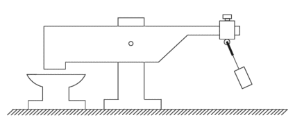
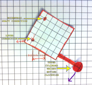
William Frank Skinner was a prolific inventor during the early 1900’s. He was the proprietor of Skinner Manufacturing Company, Inc., in Miami, Florida.
His inventions include a toy moving picture camera, refrigerated water cooler, pulsed alkaline battery rejuvenator, amongst many other inventions.
One invention that made the national news, but apparently immediately disappeared because of its highly disruptive nature is his Gravity Power Machine.
The basic claim is that Mr. Skinner is inputing power from a 1/8 HP electric motor and the output is claimed to be multiplied by 1200%. The output is going to a belt driven lathe and a couple other shop tools that would normally require several horsepower to operate. All that work performed for less than 100 watts.
Here is a copy of one of the nationwide newspaper articles:
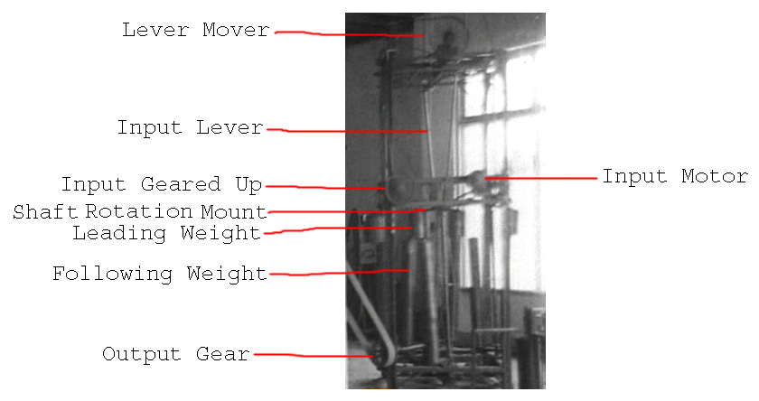
Although the claims are extraordinary, by carefully examining the machine in the video and reading the above article, we can deduce exactly what Mr. Skinner had accomplished so that we can create a replica. Let’s take a look at the main parts to the Gravity Power Machine:
Input is 1/8 HP electric motor.
Geared up input wheel is belt driven from the Input Motor from a 1/8” diameter cotton thread.
Input geared up wheel drives a belt that turns the Lever Mover, which moves the four levers back and forth.
The first three steps are simply to move the Input Levers back and forth primarily with a bit of rotation at the top of the lever. This could obviously be done in a number of ways. The back and forth is the primary motion and the slight circular motion of the level from the top increases the effectiveness of the primary mechanism.
My proposed method would be to have a Scottish Yoke assembly to convert rotational movement from a prime mover into linear back and forth movement. There are all kinds of speed controlling mechanisms available today that Mr. Skinner did not have so we should be able to greatly simplify the lever action. And of course we want a lever long enough so that the smallest input is leveraged to the max.
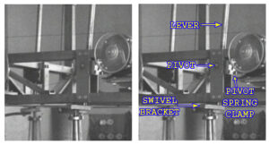
4. All the real action starts by the Input Lever rocking back and forth and having that movement leveraged slightly below the pivot point at the bottom.
When the lever is moved back and forth, its movement pivots around the pivot point. It is not clear whether or not the lever is directly connected to the pivot or is simply clamped there by what is labeled as the “Pivot Spring Clamp.”
In the video, the lever is not solidly locked to the spring clamp as there is some “give” in both directions. It appears there is some sort of “give” mechanism such as a spring, leaf spring or other setup to possibly act as a dampener but also to assist in the leverage process. The spring clamp may be directly connected to the pivot and the lever may possibly be simply clamped in the clamp.
Although this is speculation, it does not take away from the observable fact that the bottom of the lever is moving the swivel bracket. The spring clamp doesn’t appear to be necessary for the primary operation of the machine but is there to enhance the functionality.
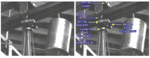
5. Looking closely at the swivel bracket, we can see that the diameter of the lever connection is smaller than the lever. So, it is possible that it is the same rod that is simply machined to a smaller diameter for practical purposes for fitting into a bearing in the bracket, or, the lever is disconnected inside of the spring clamp and a separate smaller diameter rod extends from the spring clamp down to the swivel bracket. This lower lever connection is one of three apparent connections to the bracket. The other two are a fixed connection to the upper cylinder weight, which rotates with the swivel bracket. And the other is the lower eccentric wobble shaft, which is connected to the bracket and the bracket freely rotates around this lower shaft.
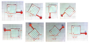
We can see this clearly in the picture below:
This swivel bracket is where all the real action happens.
As the cylinder weight that is fixed to the swivel bracket swings around in a clockwise direction (from a top down view), its momentum obviously has a tendency to keep it swinging in a circle. This is very important. When the lever is pushed in one direction, it is pushing one corner of the square swivel bracket and that moves in unison with the weight moving in a clockwise direction and when the momentum of the weight pulls it around towards the other direction, it helps to pull the corner that the lever is attached to in the opposite direction.
What this means is that the back and forth reaction of the lever is translated into rotational motion of the swivel bracket. And that shows us that the reaction of the back and forth helps keep the upper weight rotating in the same direction without it being opposed.
Furthermore, as the upper weight is pulled in a circle, it reinforces the lever’s input instead of counter it.
What we have here is an example of an apparent violation of Newton’s Third Law of Motion where the reaction actually assists the machine to perform in the forward direction instead of countering any movement. This is consistent with other known working mechanical amplifiers such as Veljko Milkovic’s 2-Stage Mechanical Oscillator and Fernando Sixto Ramos Solano’s Force Multiplier System where all the reaction in the system is diverted in a way so that it assists the system’s function in the forward direction.
As there is energy dissipation by the rotating upper weight, the lever only needs to input enough to make up for the loss in momentum of the weight, which is very little. Therefore, for a very small periodic input, two times per full rotational cycle, we are getting the full amount of work from the very heavy weight.
Look at the sequence of the steps with the weight rotating clockwise in relation to the pivot point from the lever that simply moves back and forth.
Steps 1~7 are the entire sequence and the 8th step is a repeat of the first to show the complete cycle. The below pictures shows you what each part of the swivel bracket is.
Step 1 – The lever point is to the far left and the weight is to the far right with momentum swinging it in the clockwise direction.
Step 2 – The lever point is still in the left position and the weight is still swinging around.
Step 3 – The lever point is in the same position but the weight is still swinging around.
Step 4 – At this point, the lever point is able to move towards the right direction. When pushing on the bracket from that corner in the right direction, it is in unison with the weight already moving in the clockwise direction. They reinforce each other.
Step 5 – The lever point is at the far right and the weight is at the far left.
Step 6 – The lever point is at the far right and the weight is still swinging around.
Step 7 – As soon as the bracket is situated so that the lever point can move in the opposite direction and move in unison with the weight, it moves towards the left.
Step 8 – Back to position 1.
Again, the momentum of this upper cylindrical weight carries it in a clockwise direction and this mutually reinforces the back and forth movement of the lever’s action. They are in a positive feedback cycle with each other. This translates back and forth motion to rotational movement and the rotational movement assists the lever’s back and forth movement.
As you can see, the weight is not moving around a fixed point of axis, it is moves to the left and right. It is rotating around an axis that is to the left half the time and then to the right half the time. That is the two input pulses from the lever per full rotation.
From the same sequence of steps, we can see that the point at which the lower eccentric shaft connects, it too has a none fixed orbit. Not only does the upper part of the lower shaft wobble around in a circle, it is an orbit that also has a moving axis point.
6. The next part of the trick of the system besides the Swivel Bracket mechanism is the lower weight fixed to the bottom axis of the lower shaft.
The long cylindrical weight is on a bracket that is fixed to the bottom of the lower eccentric shaft. That appears to be the only place that the lower weight is connected. It is also slightly angled outwards. With this weight, it will always try to position itself to be on the inside of the inclined shaft.
As the upper cylinder weight fixed to the Swivel Bracket rotates, the eccentric shaft is connected to the opposite corner of the bracket. The upper weight leads the bracket around and this causes the eccentric orbit of the lower shaft to constantly follow it. Therefore, since the eccentric shaft’s position is constantly changing, the lower eccentric shaft weight is constantly moving to a new center of gravity.
As long as the upper weight continues to circle, the lower weight will continue to follow.
The eccentric shaft has a fixed axis at the bottom and is connected by some means of gears, belts, etc… to a central wheel what turns the long shaft at the bottom left of the above picture. That is the output shaft and it’s power is taken from the large belt that goes to running the lathe.
To summarize, we are leveraging leverage.
We use a very small amount of energy to rock the lever back and forth. With enough length, it takes very little energy to move its connection to the bracket back and forth. The lever’s movement in conjunction with the upper cylinder weight self-reinforces each other’s movements. The back and forth movement is reinforced by the eccentric movement of the weight. And the weight’s eccentric movement is reinforced by the very small input from the back and forth movement of the lever.
As the Swivel Bracket rotates from the above stated action, the lower eccentric shaft’s connection is put on an eccentric orbit, which constantly follows the upper weight’s orbit. This causes the lower eccentric shaft’s weight to follow the upper weight producing torque at the bottom of it’s shaft that can be tapped by an output shaft.
Lever movement > moves bracket > upper weight reinforces lever’s movement > causes eccentric shaft orbit causing a moving center of gravity > lower weight constantly moves to the moving center of gravity causing mechanical shaft power at the bottom.
No laws of physics are violated. It is an open non-equilibrium thermodynamic system that is open to free gravitational potential. This gravitational potential is able to constantly act as a source of work energy on the lower weight because of the constant shifting of the center of gravity that the lower weight is seeking.
From a little input on the lever, we are able to massively amplify the amount of work we can take from the output by the described mechanism. This appears to be the highest COP (coefficient of performance) mechanical amplifier that has ever been revealed to the public.