The video below is a dual plasma ignition system – symmetrical and in parallel to give a plasma impulse to 2 different spark plugs 180 degrees from each other. It is for an experimental engine, which has 2 cylinders.
This video is recorded in hi-def so you can see it clearly if you open it to full screen. Please give a like and subscribe to my YouTube channel.
About 17 years ago, Lawrence Kennedy introduced me to some video tapes of Stanley Meyer and Roger Billings who were working on water fuel technologies. Lawrence knew both of them because he used to tour on the same lecture circuits.
Some of the videos of Stan Meyer were never seen online for many years after that, but like most people, I was sucked into the whole story about the dielectric separation of water molecules, which means electrostically splitting water without conventional electrolysis.
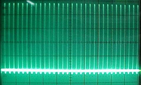
It made perfect sense and I had suggested some small scale experiments using scaled up versions of John Bedini’s radiant oscillators that output high voltage spikes, which normally charge batteries. The tests were successful as far as proving the point, but have to be taken to another level to be practical. The following image is an example of the output of an oscillator that I built back in about 2000 before most people ever heard of self-oscillating versions of Bedini’s SG circuits. That scope shot is upside down because the high voltage spikes are actually negative.
Radiant Oscillator
It only takes a small search to find that most of the Stan Meyer research online is obsessed with his VIC (voltage intensifier circuits) and resonance in order to create abnormally high amounts of commonly-ducted water gas (HHO). The problem is, this has absolutely nothing to do with what Stan Meyer was originally doing. None of the high voltage water splitting methods were around until much later in his research and its an indisputable fact documented by his own patents and other paperwork.
The other problem is that when this fact is brought up to all the self-proclaimed Stan Meyer experts, they go ballistic, literally.
I believed in this too, but was always open to learning whatever I could that was contrary to my current beliefs – and being teachable is what allowed the right teachers and answers to appear at the right time.
Years ago in Energetic Forum, there were many discussions about Stan Meyer and water fuel in general as well as a handful of people claiming to have figured it all out. But these people who “figured it all out” have one thing in common – they all have a 100% success rate in failing to show anything significant.
This is not to say that someone can’t have something valuable to contribute, but when they go out of their way to slander, defame and threaten others just because something is proposed that is contrary to what they are extremely attached to, it gets a bit ugly. One of these people even threatened my life after I revealed his identify – that is Ed Mitchell.
Here is an example of a video that is claimed to be an amazing amount of HHO production with the VIC type circuits posted by someone that has posted countless misleading claims over the years about what Stan Meyer did.
You can fast forward to 1:10 and in a few seconds, you can hear the production is “very, very fast”. This is Ed Mitchell’s nonsense.
Now, here is a single tube test I did years ago producing more gas than all those tubes above combined using nothing more than a variac with full rectified AC to DC and the ground line has a coil of wire used for current restriction. The tubes are conditioned, which I’ll mention in a moment.
Forward to 0:30 seconds to see it kick on. That is only one of of multiple tubes connected.
As the video says, Meyer didn’t really claim to condition his tubes, but he did post that he was wanting to insulate them with Delrin and other methods to prevent current. In any case, I did find that I was able to get a lot of gas production from a little input but this isn’t even the main point to this post.
Many people tried this but it wasn’t until Ravi, a brilliant engineer who started to post his replications of my work that people took notice. Many people tried to rewrite history about who did what and you can see what Ravi has to say about it himself here:
Ravi WFC Aaron
This is posted simply to maintain the accuracy of the history and to show that Ravi did not learn it from Dave Lawton as is often claimed by others.
If you are interested in my tube conditioning process, you can search my videos on both my channels for the tube videos:
Now, in Energetic Forum, Michael J.N. and Tutanka were mentioning the importance of nitrogen and I was completely open to learning what they wanted to share. Michael had built a jet engine that runs on water about 25-30 years ago at this point during at time that Stan Meyer was traveling to the UK. He knew Stan Meyer and Stan admitted to him that his exhaust smelled like ammonia. I have personally met a good handful of people that personally worked and met with Meyer and they all concur that Meyer’s exhaust did indeed smell like ammonia and nitrogen was indeed important to the process of creating a synthetic gas on demand.
Here is my replication of the jet engine system and I didn’t even get to modifying any of the steam to turn it into syngas yet at the time, but you can see that I was able to bring the propane down to 0 psi on the gauge. The gauge is too big to see how much so it is still running on propane but just traces. I started out with 8 psi before the mods and again, I got that far without even modifying the water vapor, yet:
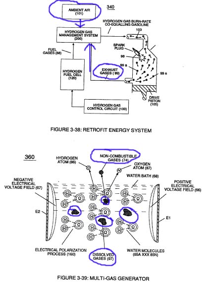
Meyer did mention that he used “non-combustible gas” to slow down the burn rate of the hydrogen gas in his process so that he can get it to burn more like gasoline. If you have experimented with hydrogen gas, you know it detonates and does not combust so you cannot get the real thermal energy out of it. The Meyer “experts” spreading disinformation online will tell you that nitrogen is not the non-combustible gas, especially Ed Mitchell – he expressed violent opposition to it as evidenced by all his posts in Energetic Forum including threatening my life as I mentioned.
I already knew about the non-combustible gas reference and it was a member named “Rock” who brought it to my attention that Nitrogen was actually spelled out in Meyer’s earlier work so it wasn’t speculation. You can see in Meyer’s earlier work he spelled out Nitrogen and later in his work, he removed the word Nitrogen and only referred to it as a “non-combustible gas”.
Many people applaud hydrogen cars for having water as an exhaust, but that is only showing you evidence that they destroyed almost all of the thermal energy they could have received from the hydrogen had they PREVENTED the formation of the water molecule. That is the key to the Stan Meyer technology.
Let’s look at what Meyer’s patent say:
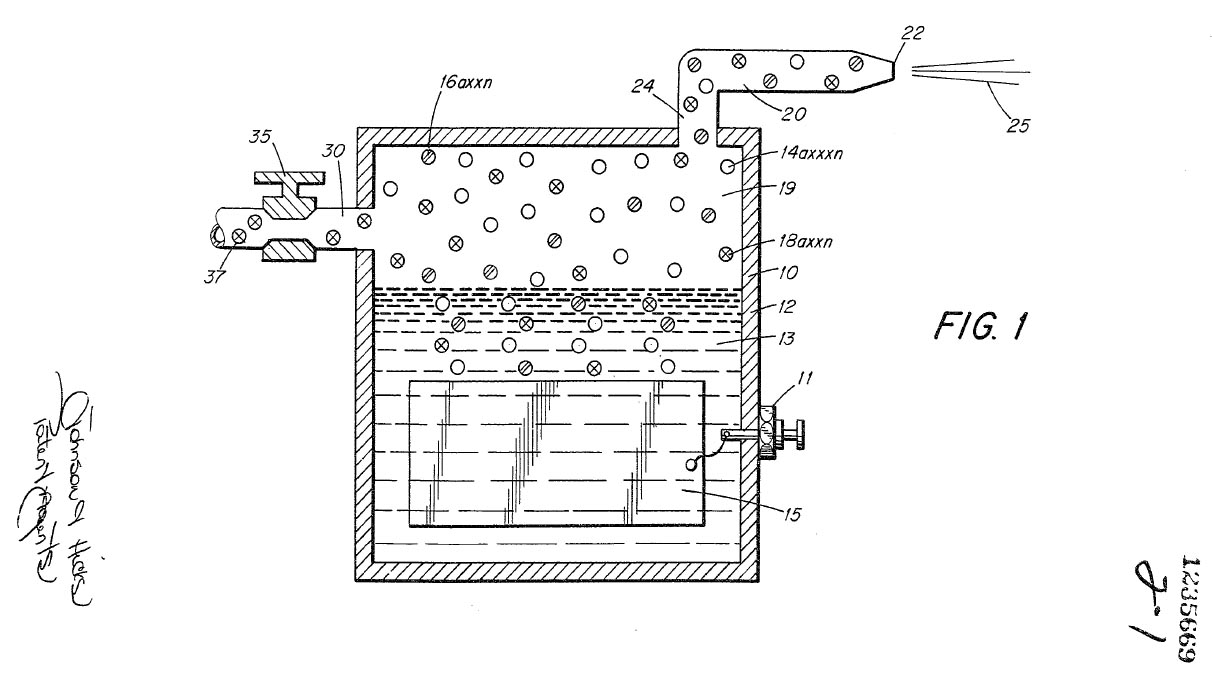
At this link: http://www.google.com/patents/CA1235669A1 you can see it clearly states, “The flame 25 is sustained in that the NITROGEN gases 16 a xxx n REDUCES THE VELOCITY AND TEMPERATURE OF THE HYDROGEN GAS 14 a xxx n.”
When you dilute the water gas with nitrogen, the ignited hydrogen will bind to nitrogen and create NH3 (ammonia) and that prevents the formation of the water molecule. It also allows the hydrogen to burn slower so that it is more like a slower gasoline combustion instead of a fast hydrogen detonation. Where did Meyer get the idea about controlling the hydrogen burn rate? We’ll get to that later because it is very important – speculation, but when you see it, it may appear overly obvious.
Believe it or not, Ed Mitchell and other self-appointed experts boldly claim that Nitrogen has no part of the Meyer process.
“The gases that are called “ambient air gases” are gases that are dissolved in water at the time when the water is being broken down and are nothing more than trace gases and can be ignored.” – Ed Mitchell
Yes, Meyer did talk about dissolved trace gases and nitrogen. Meyer claimed water had 17% nitrogen, but it is much less. You will see in a bit that Meyer also states that for REALISTIC and PRACTICAL application of the principles that the ambient air is literally from the air because the real amount of usable nitrogen dissolved in the water is UN-REALISTIC & UN-PRACTICAL.
Some of those gases are dissolved in water in quantities much less than what Meyer claimed, but the point is that the ambient air with the NITROGEN used to dilute the water gas to slow its burn rate down was literally from the air. Not only can it not be ignored as the misinformation agents will have you believe, it is the KEY to Meyer’s creation of a synthetic water fuel.
Meyer Ambient Air
Look at the top part of the image, the AMBIENT AIR coming into the system that has the NITROGEN literally comes from the ambient air, which is from the air intake and is common sense and obvious that it is not dissolved gases in water! While Ed Mitchell and others spreading disinformation tell you to ignore nitrogen altogether, it is the VERY key to Stan Meyer’s synthetics fuel on demand. Meyer even uses the term synthetic gas even though the self-appointed “experts” continue to deny this fact.
“I just wanted everyone to see with there own eyes that Meyers systems didn’t have nitrogen in them.” – Ed Mitchell
Here is a YouTube comment by Ed Mitchell
“+Matt McMahon Inventor If you manage to get the Nitrogen theory working you will have done the impossible Matt. As that BS theory the way you all want it to work breaks untold numbers of rules and laws of science. Now do as the good Max as instructed you to do and study or stay out of our way. A lead for you. If you don’t make use of the scientific method on this one you will fail as there is no getting around it as no amount of guessing is going to solve this technology for you.”
“There’s nothing to see here folks – move along!” – that is the method of operation (M.O.) of the disinformation agents who are spreading lies, rumors and myths online doing their best to not let you see what Meyer was saying in his own words. They’re all Meyer experts but they deny the most important things that Meyer said in his own documents.
They jump into the middle of Stan Meyer’s work bypassing everything he did in the beginning and they call that scientific?!
You can see the constant attempts by Ed Mitchell and others in his circle are constantly trying to do what they can to deter you from learning about the Nitrogen key, but here you are with Meyer’s own words and these are just a few of MANY snippets from his documents.
In Meyer’s documents, he defies what he means by non-combustible gases.
1. Nitrogen dissolved in water, which he says is not practical or realistic to use because the amount is too small.
2. Nitrogen from the ambient air, which is 78% of the contents.
3. Recycled exhaust.
Here is a direct excerpt from Meyer’s documents showing you that he was creating a SYNTHETIC GAS and water gas by itself is NOT a synthetic gas. Creating ammonia type fuel by modifying water gas with nitrogen from the air IS a synthetic gas.
What you see at the top left is a mixing valve to let in ambient air from the ATMOSPHERE and NOT ambient air gasses dissolved in water as Ed Mitchell claims.
This is what the patent says about it:
“Natural water such as tap, well, sea or fresh water is an absorber of ambient air. Ambient air in turn contains a substantial amount of nitrogen gas. Water as an absorber of ambient air will entrap seventeen percent (17%) of nitrogen gas; that is natural water absorbs seventeen percent (17%) of nitrogen gas in comparison to its hydro- gen and oxygen gas content. In operation of the hydrogen generator the gases in the water will be released. Therefore, when natural water is used the air will be released together with the hydro- gen and oxygen gases. In the preferred embodiment utilizing tap water, the nitrogen gases 16a — 16n are intermixed with the hydrogen gases 14a — 14n and the oxygen gases 18a— 18n in the chamber 19 of the hydro- gen generator 10. Upon release of the gases via line 24 and nozzle 20 and then port 22 the gas mixture is ignited to provide a flame 25. Flame 25 is sustained in that the nitrogen gases 16a — 16n reduce the burning velocity and temperature of the hydrogen gas 14a — 14n. A realistic and practical manner of further con- trolling the burning velocity and temperature of the hydrogen gases 14a — 14n is by adding non- combustible gases directly to the hydrogen and oxygen gases generated. This is accomplished by inlet 30 to the upper gas chamber 19 of the hydrogen generator. Valve means 35 is adjustable to control the amount of non-combustible gases 16a — 16n added to the gas chamber 19. The nozzle 20 connected to the chamber…”
The FIRST blue highlighted section shows that dissolved nitrogen in water will indeed mix with the freed up hydrogen and oxygen. Meyer is wrong about water containing 17% nitrogen though, it is much less.
The SECOND blue highlighted section shows that Meyer is stating that the nitrogen controls the burn rate of hydrogen.
The THIRD blue highlighted section shows a REALISTIC AND PRACTICAL manner of really controlling the burn rate of hydrogen is by directly mixing the water gases with ambient air from the atmosphere. In this old original patent, he did it by letting air come into the top of the cell, which is certainly NOT traces of nitrogen dissolved in water as the online disinformation is trying to make everyone believe.
Now, just because Meyer started out diluting water gas with Nitrogen, this does not mean that trying to create high amounts of HHO is a bad idea.
This was before Meyer ever went the route of the VIC to try to produce more water gas for the same electricity. You can see the patent doesn’t even use concentric tubes in his cell but flat plates and he has even earlier patents where the electrodes are simply 2 pointed rods with a gap between them submerged in water. Most people are starting their studies with Meyer’s technology with concentric tubes and the VIC completely throwing out the window what the whole point was – to control the burn rate of hydrogen to get the thermal energy out of it so it burns like gasoline (slow) instead of a fast detonation.
I’ve created water gas hundreds of percent beyond Faraday and it is still not enough to run an engine and that was never what Meyer did. It wasn’t about QUANTITY of gas, it was about QUALITY of gas. He also recycled the exhaust back to the intake to condense and build up that supply of ammonia to act as the source of hydrogen. There is no magic here and no natural principles are violated.
As long as you can crack hydrogen from the ammonia and there are many tractors, etc. running on ammonia just fine, then you can continue to use the exhaust as a supplemental fuel source that condenses over time.
If you do want to get more details on this entire process, you can get my Water Fuel Secrets package here: http://waterfuelsecrets.com but honestly, there are enough priceless bit of information above that if you just searched it long enough, you’ll find all the references to see that what I am saying is 100% accurate as far as my claim that this is exactly what Meyer is spelling out in his patents and Nitrogen dilution of the water gas absolutely is indisputably THE KEY to his synthetic fuel on demand that allowed the water gas to burn like gasoline instead of detonating like normal.
I hope you enjoy and appreciate the information shared above. There is more truth about what Meyer did posted above than in most websites on Meyer’s technology combined. I’m not trying to compete with anyone, I just have no tolerance to misinformation when the truth is right there in front of everyone in readily available public domain documents! This is not some discovery unique to me and I have to give credit to those who helped point me in the right direction.
Recently, I have been in touch with someone that has an interest in this water fuel concept and my plasma ignition and during some discussions, he pointed out some very interesting items from someone’s work that goes back before Stan Meyer was born.
He’s getting it all prepared and when I announce it, I will make another blog post here pointing out a few things about that work and why I think it is an absolutely priceless study. When this person pointed out some of this old work, it looked fairly obviously to me that Meyer had studied the same work and that is where he got the ideas about controlling the burn rate, recycling his exhaust and Meyer even mentions in his documents that he could close loop his whole system. It appears to be THE GENESIS of all of Meyer’s work in regards to controlling the burn rate of hydrogen, etc. as it looks like a natural extension of the work of one particular historical individual who is surrounded with mystery, tales and it wouldn’t be complete without a bit of conspiracy!
The good thing is, that person’s original work still survives and some people have working models and I’m looking forward to announcing this soon. The implications of being able to really put this technology on the map is huge. Not enough people know about it but soon, my hope is that you will join me in spreading the word about it far and wide! PLEASE USE THE SHARE BUTTONS BELOW TO SHARE THIS ON FACEBOOK, TWITTER, ETC.
Here is a short video with an explanation of the analogy between the Gray Tube switching method and my (Aaron) particular version of the Plasma Ignition.
We have finally enabled comments in our blog here at http://emediapress.com.
At the bottom of any blog post, simply click in the field to comment and you can post comments through the DISQUS system, which you can log into through Facebook, Google+, etc…
It is a great comment system that will help prevent spam and you don’t really have to sign up for anything new if you’re a member of Facebook, Google+ or other sites that integrate with DISQUS.
Here is an invitation only call to answer questions about the Bedini SG books. Only those who have the books were invited to the call. We just made the video public so even if you don’t have the books, you can learn a bit more about the Bedini SG.
You can get copies of the books here – the Trilogy is the best deal: Bedini SG
Many conventionally trained academics deny the possibility that a machine can produce more work than we’re required to supply on the input. As long as a system is open to the environment where more potential energy can enter the machine, then more work can be done than we had to pay for.
The downfall to conventional academia is that the concepts of energy and potential energy are taught completely backwards and there is no accounting for what the actual source potential for electrical charge even is or where it comes from.
Once the distinctions are straightened out, then we can see that not only is it possible to create a free energy machine, if we build them according to the natural principles of open systems, it is practically a requirement for them to output more than we have to input.
Closed system thermodynamics as taught in school only apply to closed heat systems, yet the entire field of physics, etc. try to apply it to electromagnetics, mechanical systems, you name it. The fact of the matter is that conventional closed system thermodynamics actually do not even apply to any natural system in the Universe – because every natural system is open to other sources of potential energy!
We recommend reading a copy of The Quantum Key by Aaron Murakami as a basic primer that explains the reality of free energy systems in terms so simple, only a junior high school level understanding is needed.
The Quantum Key is actually a simplified Unified Field Theory for the layman that links gravity, inertial, electricity, mass, light speed, etc… all together in a seamless manner and even gives a simple explanation of what Time may actually be. Make sure to at least read the descriptions of the chapter on the website below!
This book is available at a hugely discounted price, which will change soon, so make The Quantum Key a part of your library – its a perfect companion to the Bedini SG Trilogy!
The Bedini SG is a “right of passage” for anyone that wants to learn how to actually build real Tesla technology in miniaturized form. It is the best way to start for anyone that is new and even seasoned engineers have a thing or two to learn from it.
Here is a free download that includes Chapter 1 from Bedini SG – The Complete Beginner’s Handbook: Bedini SG
It also reviews the Intermediate and Advanced books and discusses why knowledge of the Bedini SG is a * MUST HAVE * – especially if you’re interested in preparing for the future.
Tesla’s Technology Miniaturized And Simplified For The Masses
Legacy of a World-Class Inventor & Humanitarian
Spokane, Washington – November 2, 2014
Fifteen years ago, Shawnee Baughman of Coeur d’Alene, Idaho was competing for an elementary school science project and an electronics wizard happened to work in the same building as her father. She was provided with a simple schematic and a bit of coaching. With that, she went off on her own to build a little motor that spun a wheel, lit an LED light, and ran from the same 9 volt battery for the entire five days of the science fair.
Shawnee won a Blue Ribbon for the science, and a special award for Best of Show, and ever since that time, the machine has been called the “School Girl Motor” or the “Bedini SG” for short.
John Bedini is an internationally acclaimed audio engineer who has many claims to fame, which include developing the first solid state audio amplifiers that actually replicated the sound qualities of the old vacuum tube models. But his favorite hobby has always been the study of advanced energy conservation methods using unconventional electromagnetic principles that most engineers have never heard of.
The Bedini SG has since taken the world by storm, spreading far and wide across the internet, and allowing countless thousands of people to build their own model and study the physics involved. Just about anybody can get one to spin, but only a handful have ever achieved a level of performance that demonstrates what some would consider “free energy.”
Many experts claim this is impossible, but actually there are many systems that produce more work than we’re required to supply, because the excess energy is provided by the environment. A good example of this is the refrigerator. This ordinary kitchen appliance typically operates with a “coefficient of performance” of 2.0, which means that twice as much heat is removed from inside than the equivalent electricity used to do it. Most scientist believe that this kind of performance is only possible with heat systems, but John Bedini and others have demonstrated these principles with electromagnetics as well.
In 1977, Ilya Prigogine received a Nobel Prize for what is basically an extension to conventional thermodynamics, which only describe how heat operates in “closed systems.” Those are systems that are cut off from any external form of energy. Prigogine’s work helped to extend our understanding of thermodynamics to include systems that are open to the environment, which slows the appearance of entropy down and allows more total work to be done than what we have to supply. That is exactly what the Bedini SG demonstrates in a simple and most elegant way.
Several years ago, A & P Electronic Media, a digital publishing company founded by Aaron Murakami and Peter Lindemann published the first ever authoritative book on Bedini’s technology. Murakami and Lindemann have collectively known John Bedini for over 45 years and both have been personally mentored by him.
Their first book outlining the basics of this technology is Bedini SG – The Complete Beginner’s Handbook, which includes all of Bedini’s own personal specifications for building his machines, as well as an in depth explanation of the science and theory behind its operation. With this book, just about anyone can build a working model.
The second book is Bedini SG – The Complete Intermediate Handbook. It digs deeper into the theory of the technology and shows how John’s circuits act like miniaturizations of systems developed by Nikola Tesla over 120 years ago. What this process does is take the high voltage spikes from an electromagnetic oscillator and charge a capacitor with them. This capacitor is then discharged into a load, such as a lead acid battery.
Engineers are normally taught to ground these spikes out so they don’t damage other electronics on an electrical line. In fact, that is what a “surge protector” is designed to do. Through experimentation, John discovered that these electrical transients have a number of unusual characteristics. One of these benefits includes the ability to charge batteries extremely efficiently, and even revive some batteries that are considered dead.
Although many engineers claim these spikes can’t charge a battery because they are just high voltage with virtually no current, there are thousands upon thousands of global experiments being conducted with these circuits that prove otherwise. And if these spikes are used to charge a capacitor and then that capacitor is discharged into a battery, even more amazing results can be had. And this is one of the methods for using electricity that Nikola Tesla developed back in 1893. John’s circuits are literally a miniaturized version of some of Tesla’s greatest discoveries.
A & P Electronic Media has now released Bedini SG – The Complete Advanced Handbook. The finale to this paradigm-shattering trilogy teaches the reader how to convert the mechanical work produced on the wheel into even more electricity, in an extremely efficient way. As a matter of fact, it is so efficient that at the recent 2014 Energy Science & Technology Conference, Peter Lindemann was able to demonstrate how to light a large bank of LEDs to a very bright level without reflecting almost any mechanical load back to the machine.
This third book also reveals many details from John Bedini’s other related technologies, some of which have never been released or explained to the public before. In that sense, it also doubles as a tribute to his tireless contribution to the field of advanced energy research over the last four decades.
The Bedini SG has been around for about 15 years and it seems there is no end to the surprises that occasionally pop up that teach us one thing – we haven’t learned everything about it yet!
On November 2nd, we’re launching Bedini SG – The Complete Advanced Handbook, which shows how to make low drag generators to make the most use of the mechanical work, but there is a whole lot more.
One thing we’re going to full disclose is a special mode that John Bedini developed that allows us to increase the output by 100% with only a 50% increase of the input! How do we only increase the input energy by 50% but DOUBLE the amount that is available on the output? The Advanced book will give the entire schematic and working theory about how and why it works.
On November 2nd, we’re making a video available on the Bedini SG website where we discuss all three books but we even show a demo where the electrical output doubles by only increasing the front input by half.
If you don’t have the first or second book, just wait until November 2nd when you can get your hands on the entire triple combo pack at a huge discount!
With this third book, this trilogy will give more information about real free energy circuits than anything that has ever been published. Especially when we disclose all the circuits necessary to accomplish it.
Bedini SG – The Complete Advanced Handbook is the most highly anticipated release that we have ever made available.
Two of the most popular books are Bedini SG – The Complete Beginner’s Handbook and Bedini SG – The Complete Intermediate Handbook.
The Beginner’s book walks the reader through all of the exact specification that John Bedini uses to build his own energizers, plus is shows the difference between repulsion and attraction mode which has only been discussed in the last couple years.
The Intermediate book teaches all about Tesla’s Method of Conversion, which is taking the electrical recovery from the coil, charging a capacitor with it and discharging that to a low impedance load like a battery.
The Advanced book will cover in great detail how to turn the mechanical work of the wheel into electricity in a very low draw way but it will also reveal a few more surprises. For the first time ever, details on the famous “Watson Machine” will be disclosed that have never been public as well as details on a few other Bedini technologies. This book has the keys necessary to take everything to the next level like never before.
The release date for Bedini SG – The Complete Advanced Handbook is November 2nd, 2014.

 We recommend reading a copy of The Quantum Key by Aaron Murakami as a basic primer that explains the reality of free energy systems in terms so simple, only a junior high school level understanding is needed.
 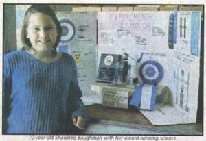 Shawnee won a Blue Ribbon for the science, and a special award for Best of Show, and ever since that time, the machine has been called the “School Girl Motor” or the “Bedini SG” for short.
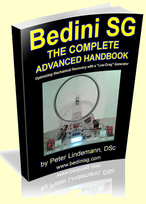 A & P Electronic Media has now released Bedini SG – The Complete Advanced Handbook. The finale to this paradigm-shattering trilogy teaches the reader how to convert the mechanical work produced on the wheel into even more electricity, in an extremely efficient way. As a matter of fact, it is so efficient that at the recent 2014 Energy Science & Technology Conference, Peter Lindemann was able to demonstrate how to light a large bank of LEDs to a very bright level without reflecting almost any mechanical load back to the machine.