Donate to EPD Laboratories, Inc. 501(c)3 – https://ericpdollard.com/donate
Category: Electronic Equipment
NEW RELEASE – 2023 ESTC Ultra Low Frequency Amplifier-Modulator – Eric Dollard, Adrian Marsh PhD, Aaron Murakami
Last year’s flame speaker was 100 watts, this year, it will be around 2000 watts. The audio modulator bay is 100% complete and the RF bay is well on its way. We have some makeshift modifications that we had time to complete for the conference. We’ll continue to completion after the conference. There will be multiple demonstrations with this universal, high frequency and high voltage test equipment. Watch the preview video below for a sample of what is demonstrated.
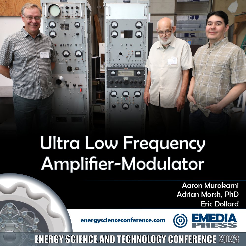
Ultra Low Frequency Amplifier-Modulator
Last year’s flame speaker was 100 watts, this year, it will be around 2000 watts. The audio modulator bay is 100% complete and the RF bay is well on its way. We have some makeshift modifications that we had time to complete for the conference. We’ll continue to completion after the conference. There will be multiple demonstrations with this universal, high frequency and high voltage test equipm…
2022 ESTC New Release – Advanced Measurement Techniques for Tesla Coils by Dr. Adrian Marsh

In 2019 when Eric Dollard presented on the 20:1 scale model replica of the Colorado Springs Magnifying Transmitter, Dr. Adrian Marsh was there to help analyze the MWO, the Colorado Springs transformer and more. He was able to quickly figure out how to get the MWO pulse modulator to power the Colorado Springs transformer and several experiments were conducted on the fly.
This year, Dr. Marsh gave a comprehensive overview of using a Vector Network Analyzer to show more information about the resonant peaks, serial vs parallel mode and more. It is must easier to obtain this information with a VNA compared to using a current transformer and analog volt meter. It’s recommended that you do understand the old-school analog method because it is important to understand that but for ultra fine tuning, the VNA is the way to go.
You’ll see a lot of charts produced by the VNA output and Dr. Marsh shares the comparison between a very affordable VNA compared to his HP one that was a $100k unit when brand new. The results are extremely close.
In addition to the VNA presentation, you’ll also see a replication of Eric Dollard’s gold-ratio high voltage discharges! This is the first time this has been replicated by anyone other than Eric to our knowledge. This was done with equipment that Dr. Marsh brought over from the UK in a suitcase.
For the exact VNA used, this is the only one recommended: Vector Network Analyzer
Go here to watch the preview video or get a copy of the full presentation: Advanced Measurement Techniques for Tesla Coils
Bedini RPX v3.0 – Presales Open February 17, 2022
It’s very exciting to finally release version 3.0 of the Bedini RPX Sideband Generator. The link at the end of this sentence takes you to the RPX page that explains the sideband technology in detail – scroll back up to this link but read this page first: RPX Sideband Generator: RPX SIDEBAND GENERATOR
Below is a sneak peak at the Bedini RPX 3.1MHz Sideband Generator v3.0. If you’re not familiar with what a sideband generator is, the above link will take you to a page that explains it. Any device that correctly produces harmonic sidebands the way that Rife and his assistant Philip Hoyland did must use carrier-wave heterodyning – this is an indisputable, historically-documented fact of RF engineering.
RPX stands for Rife, Priore and an X-Factor but it really should stand for Rife, Priore and Bedini because what his genius incorporated into the RPX is in fact the X-Factor. When we release the v3.0, you’ll learn why the RPX is far superior to any other device even remotely similar and there is only one that is close that I know of and that John Bedini truly was the world’s leading authority on what Rife was doing.
DISREGARD THIS BLOG POST, THE RPX 3.0 IS ALREADY AVAILABLE FOR PURCHASE – GO HERE FOR THE NEW WEBPAGE: RPX SIDEBAND GENERATOR
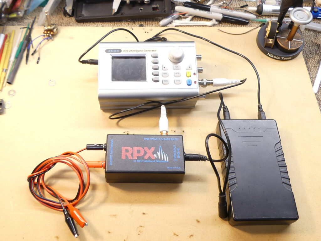
First, here’s a picture of the original unit – it worked perfect but was a bit cumbersome since you have to connect an external signal generator and external battery but this is how John Bedini originally released it late 2014 or early 2015. Below, you’ll see the obvious point to the new RPX 3.0 and why my goal was to make the most user friendly sideband generator ever developed and it has been successfully accomplished.
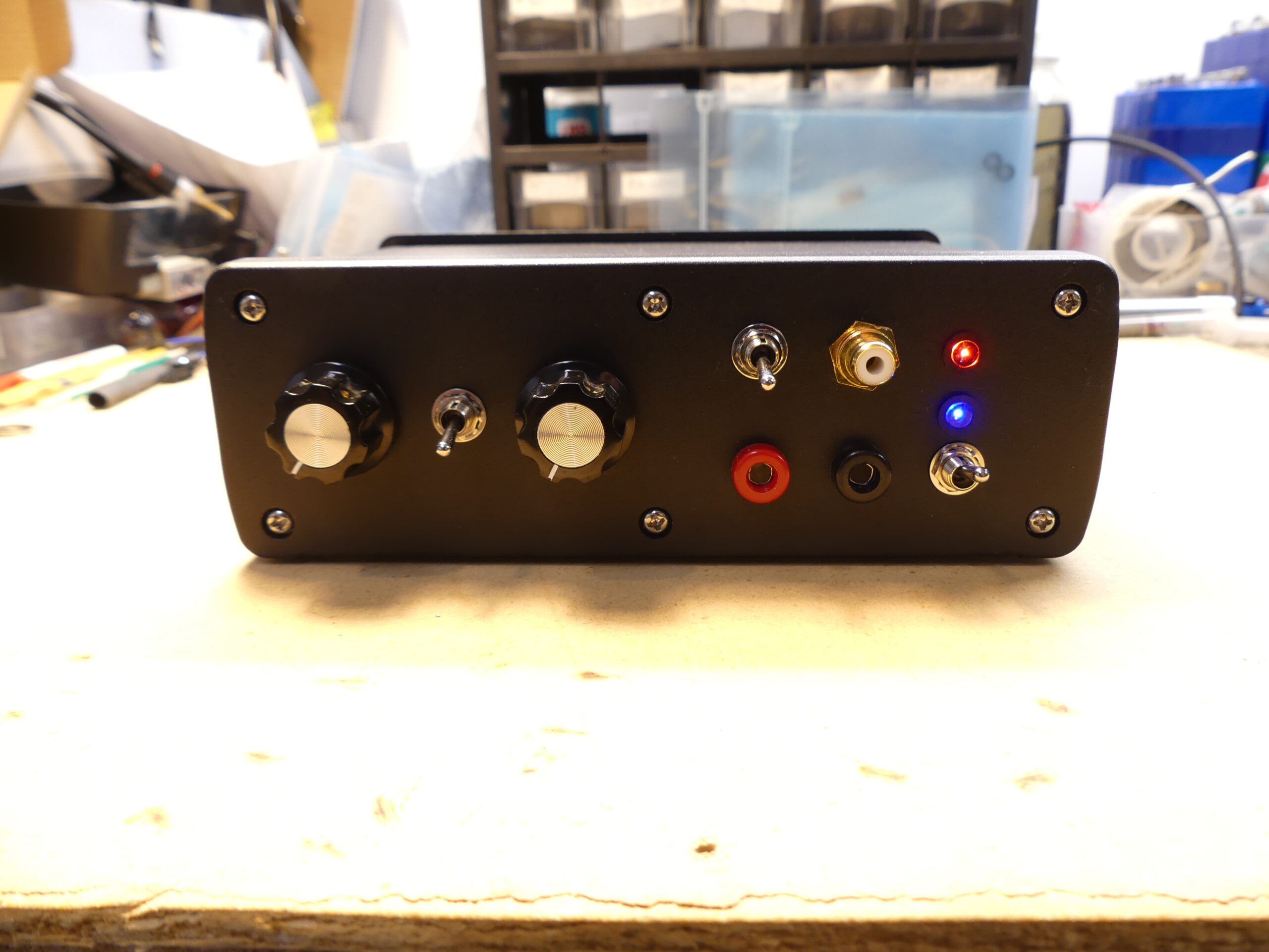
Below you can see the prototype (no logo or labels for the knobs, switches or jacks). The signal generator inside was designed by Paul Babcock so this couldn’t have happened without his brilliant help. Others were kind enough to offer their services to design one in the past but at that time, the cost was prohibitive, plus, I wanted to stay away from digital as much as possible because digital is fake and analog is of the real world. THE SIGNAL GENERATOR IS 100% ANALOG. Both Rife and Bedini would be thrilled about that!
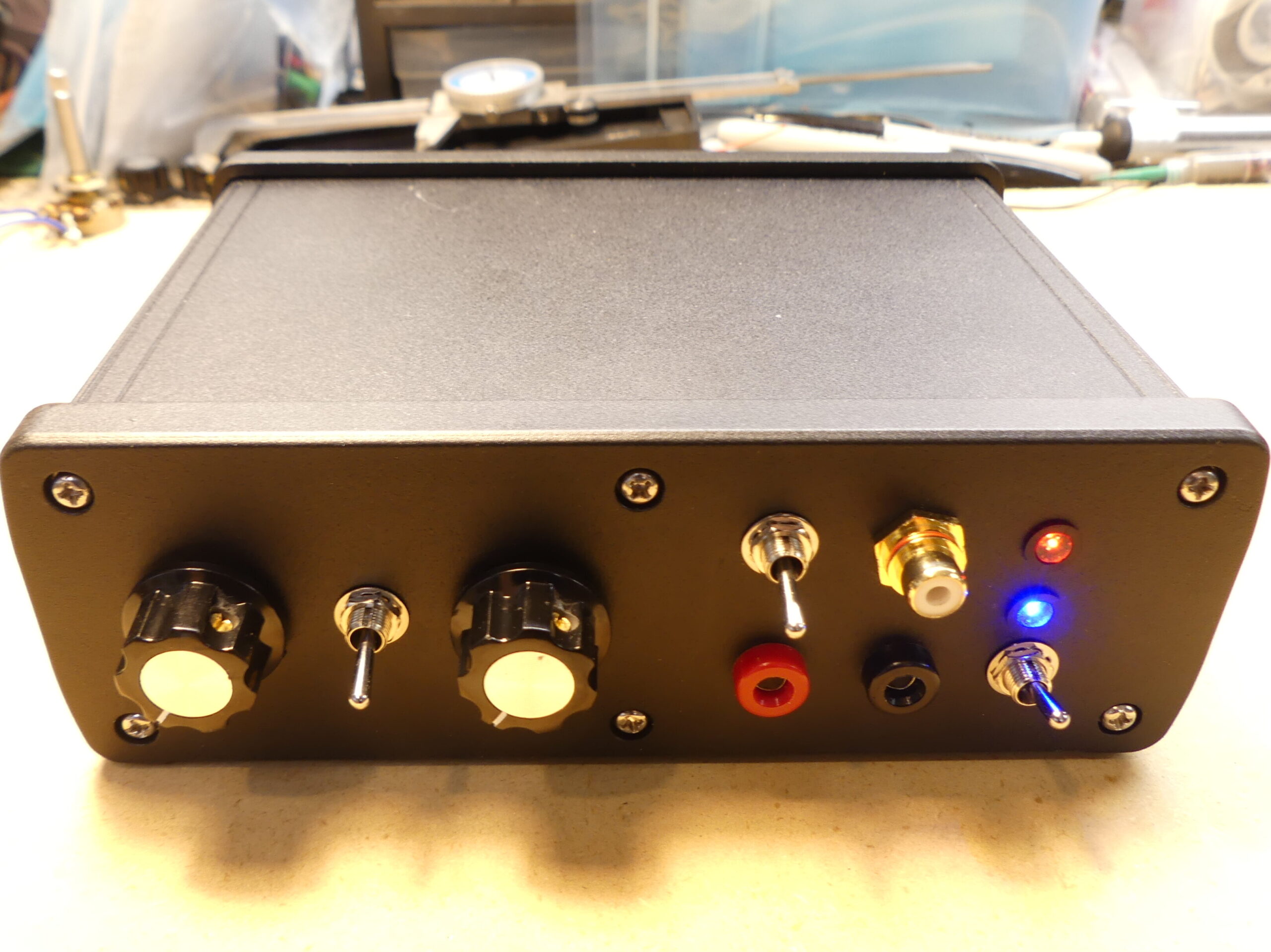
- The LEFT KNOB controls the TIME of the sweep. Specifics will be forthcoming.
- The SWITCH between the knobs in the down position leaves it in WIDEBAND MODE so it sweeps from close to 0Hz up to 150kHz to create sidebands that are even multiples of countless harmonic frequencies automatically. Rife went to 40kHz because that was the upper range of a typical audio signal generator. Why go to 150kHz? It’s one of the things that makes this superior to any other sideband generator that creates the Rife Frequencies and I’ll show the math and demonstrations for this so you understand what this means and why it is important. What did Bedini know that Rife and Hoyland possibly didn’t? You’ll find out soon on the page where these units will be available for pre-order on February 17th, 2022.
- The RIGHT KNOB controls the narrow band sweep. When the switch is in the up position, it activates the narrow band mode. I’m asked all the time about focusing on certain frequencies. It’s always a bad idea to use any single static frequency as a “wobble” or variation in the frequency was always what was found to be superior. So within the 150kHz range, the narrow band will focus on a 25-30kHz range. If the knob is all the counterclockwise, it will sweep from almost 0Hz up to about 25kHz and as you rotate the dial clockwise, it will keep a 25-30kHz sweep width but higher up in the 150kHz range. There will be a chart printed on top of the case that shows you what frequency range you are at based on the number on the dial, which will be printed on the front panel.
Scroll down to the top of the next picture for an explanation of the rest of the features on the front panel – I just want to break up the text a bit to make it easier to read.
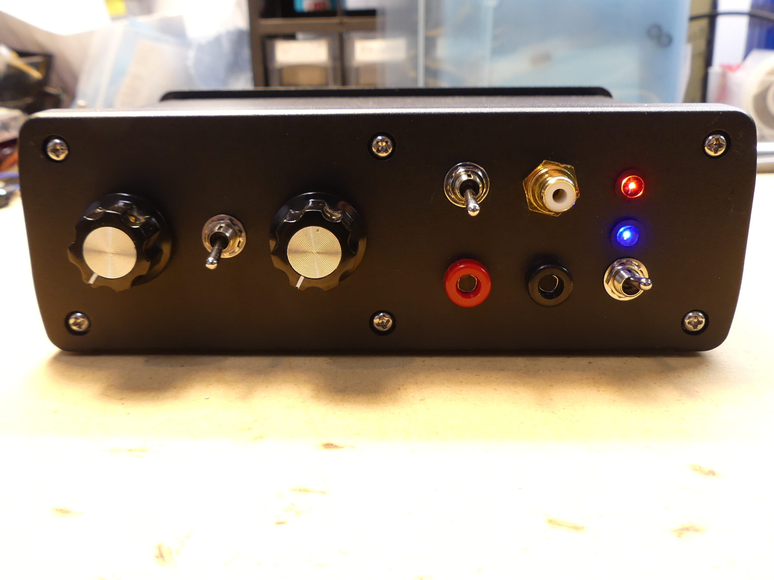
- The switch at the top next to the gold RCA jack allows you to use the internal signal generator, which is all anyone will need 99.99% of the time. In the down position, you will be using the internal signal generator and the two knobs and switch to the left. But for those of you who are more technically oriented, you can move the switch in the up position and you can then plug in your own signal generator into that RCA jack. ONLY USE SINE WAVE AND LIMIT THE OUTPUT VOLTAGE OF YOUR SIGNAL GENERATOR TO 2 VOLTS MAX or you can damage the unit. You will able to narrow the sweep to perhaps a few kilocycles on either side of a target frequency to get more specific, extend sweep times beyond what is possible with the internal signal generator or even use frequencies that will produce sidebands that are even multiples of frequencies like 432Hz or any other frequency set of numbers using this method. We’ll teach you how to calculate all that with videos that will be available.
- The RED and BLACK banana jacks at the bottom are the output jacks. We supply a cable that you can plug into that and on the other end are alligator clips. You only have to supply your own electrodes. Inexpensive copper tubing from a hardware store than you can get for a few dollars per foot is all you need. Two pieces about 4″ long and maybe 3/8 to 1/2″ diameter is sufficient. For experimental setups requiring signal transfer through conductive materials, this gel can improve connectivity – this is our Amazon affiliate link: Conductive Gel
If you’re mechanically inclined, we’d recommend cutting off the alligator clips and soldering the wires to the tubes or adding ring terminals and screwing them to the tubes. Later on, we may recommend a company where you can get some electrodes. - The top right LED light is a RED power light that shows the RPX power is turned on (switch is on the back).
- The LED directly under that shows when the PUMPWAVE is on and it will also be RED – just the prototype has the blue light and its just too bright. The switch underneath that can be switched to turn the Pumpwave off and on. This is another one John Bedini’s genius innovations. With the switch off, you get the 3.1MHz carrier and sidebands. With the switch on, you get the low frequency carrier (another carrier) that puts the 3.1MHz carrier and sidebands on it and that Pumpwave is a 8-9Hz square wave that enhances the sideband output signal. Literally, there is nothing that compares to the Bedini 3.1MHz Sideband Generator v3.0.
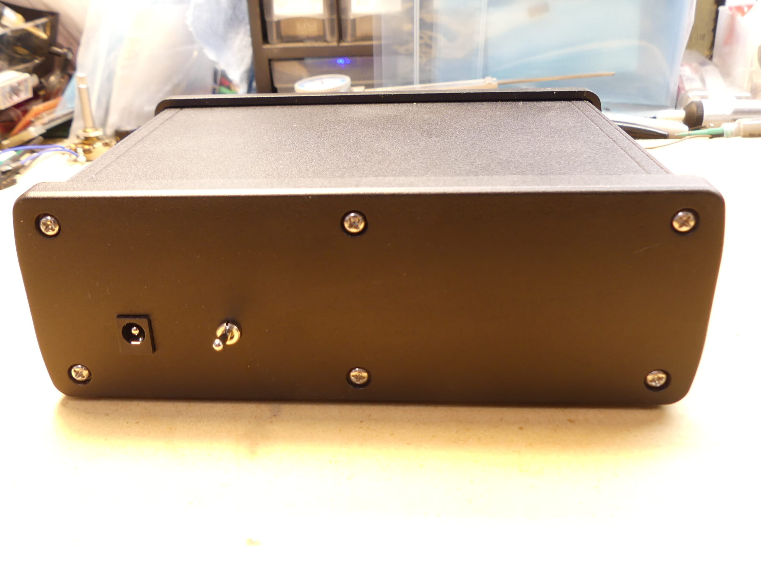
Above the next picture is a description of what is on the back of the RPX.
- The jack and switch below will be flush with the panel on the final units. The jack on the left is for a 16.8 volt 1 amp, regulated lithium-ion charger. The red light on the charger will be on while it is charging and when it is finished charging, the green light will come on. You will not be able to use the RPX while the battery is charging – plugging in the charger will disconnect the battery from the circuit. Please charge the battery fully before using the RPX for the first time. Typical experimental sessions run about 15 to 30 minutes so you will get a good number of uses before you have to charge the battery again. The switch on the right is the off/on switch to turn on the power. In the down position, it will be off and in the up position, it will be on.
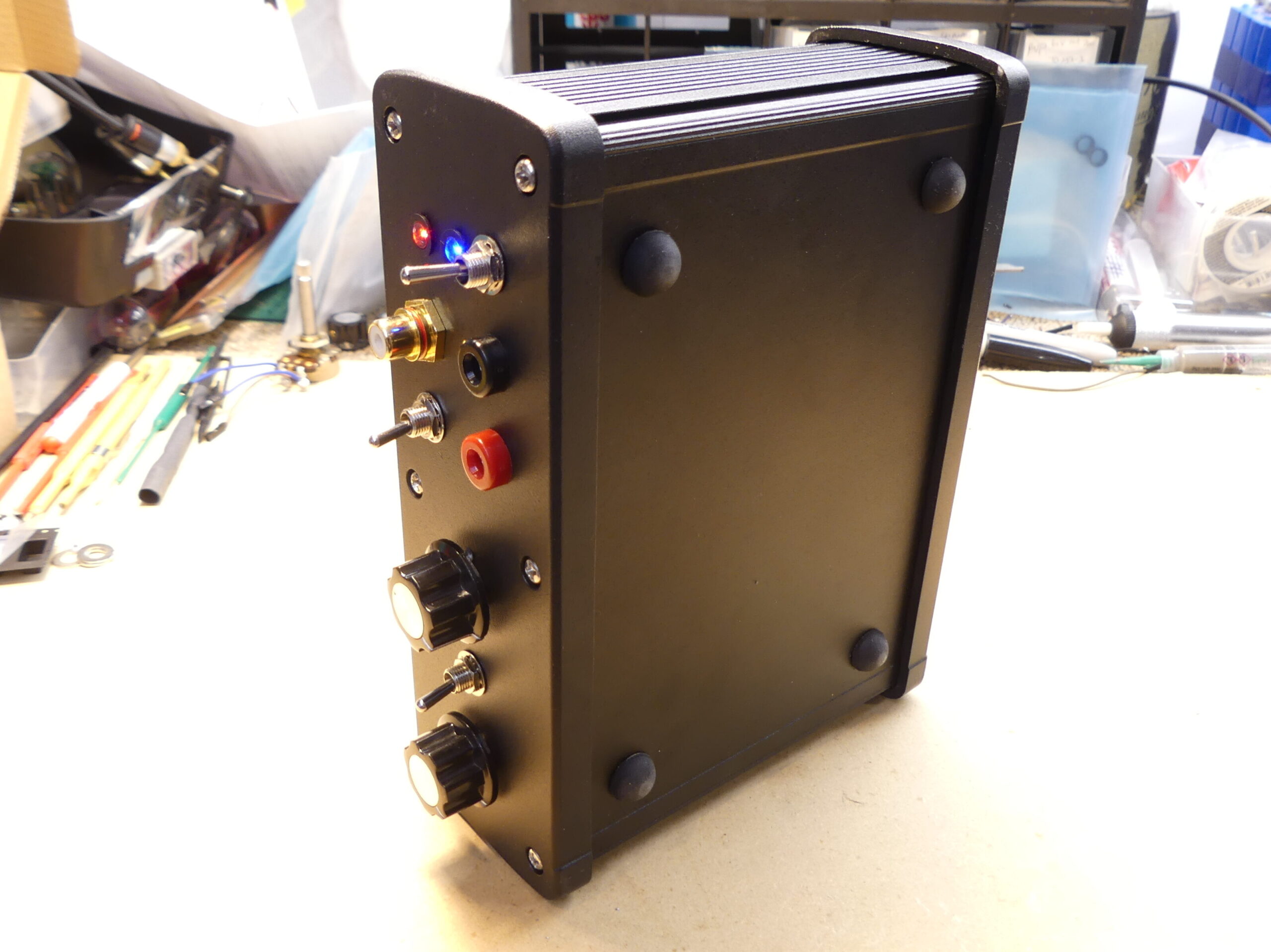
I’ll make a video walk thru and will put that on the RPX page when pre-orders are open on February 17th along with pricing, etc.
The RPX v2.0 model sold for $425 itself (required you to provide your own battery and signal generator) or $650 for the whole combo kit that included everything except the electrodes. My goal was to make this new RPX 3.0 available for as close to the RPX v2.0 price as possible. The RPX v3.0 will cost more because my production costs are higher. The first 50 (most likely 50) units for pre-sale will be at a super low price compared to what the retail price should be.
Keep in mind that the next closest machine that even comes close to a “Rife Machine” retails for over $1800. That means that since this is a superior technology and it is a super specialty item not available anywhere else that the RPX v3.0 should have a retail price of around $2000 to $2500 (but it won’t be) and it would be worth ever penny comparing value vs value in terms of sale price.
Make sure to order as soon as the pre-order page opens up on February 17th because you’ll be pleasantly surprised with our pricing! You’ll also be earning points on emediapress.com that is good for credit toward digital downloads. More to come…
Remember to go to this page to learn more about the sideband technology: RPX SIDEBAND GENERATOR
2021-05-08 Dollard Cosmic Induction Generator RF Rack Update
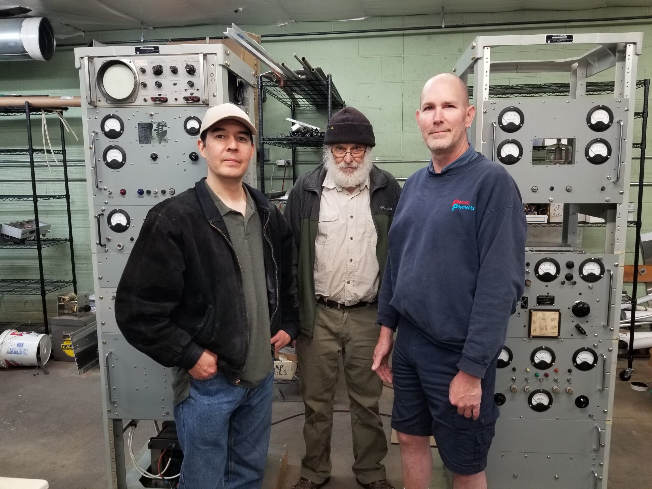
Here’s an update video of the RF rack for the Cosmic Induction Generator.
Come to the 2021 Energy Science & Technology Conference – Learn more here: https://energyscienceconference.com
Get your ticket(s) directly here: https://emediapress.com/shop/energy-science-technology-conference-2021/
Support the work of Eric Dollard here: https://ericpdollard.com
Green Energy = Gangrene Energy by Eric Dollard
Here’s a demo of how problematic “green” LED lights are.
Come to the 10th Annual Energy Science & Technology Conference: https://energyscienceconference.com
Donate to EPD Laboratories, Inc. 501(c) non profit – support the work of Eric Dollard https://ericpdollard.com
Colloidal Silver – A Closer Look by Peter Lindemann
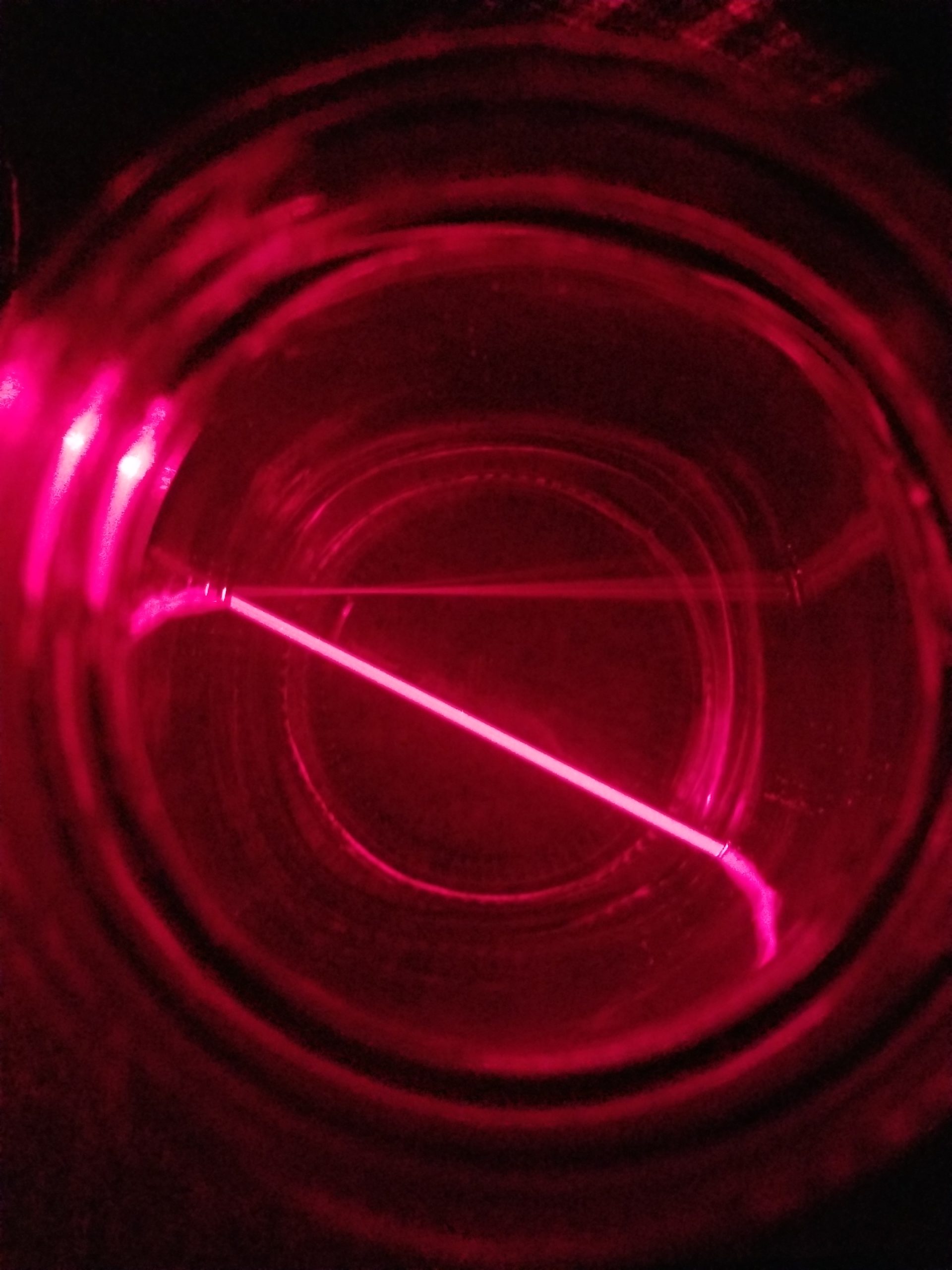
Twenth-three years ago, Peter Lindemann wrote an article on colloidal silver that was published by Borderlands and today, it remains one of the most referenced articles.
Recently, Dr. Paul Maher’s paper on the subject was released and it references Peter Lindemann’s article as well. Download Dr. Maher’s paper Silver is a Broad-Spectrum Anti-Viral here: https://emediapress.com/2020/04/01/silver-is-a-broad-spectrum-anti-viral-by-paul-maher-md/
Peter’s article is very easy to understand and clearly discusses the important to know difference between ionic and colloidal silver. I highly recommend downloading a copy from his website here: http://free-energy.ws/pdf/cs_closer_look.pdf
For other articles on Peter’s website, visit http://free-energy.ws
AMInnovations by Adrian Marsh
Adrian Marsh is very skilled with electrical engineering and has a lab where he has not only done some phenomenal work – his builds are high quality and beautiful as well! If you want not just picture and videos of experiments but hard data and a lot of technical detail based on experimental results, you must visit his website.
ADRIAN’S WEBSITE HAS TWO VIDEOS THAT ARE REFERENCED IN THIS POST – UES THE LINK PROVIDED AT THE BOTTOM OF THIS POST. AND MAKE SURE TO CHECK OUT THE REST OF HIS WEBSITE!
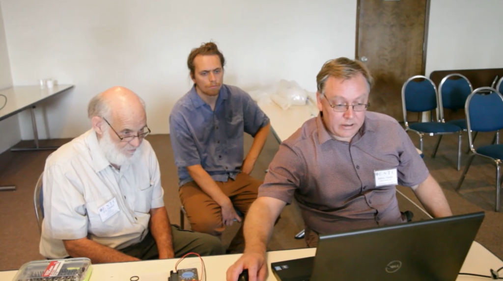
In the picture above, Adrian is explaining to Eric the waveforms that the Vector Network Analyzer is outputting from measurements of the 20:1 scale model Tesla coil replications. Raui Searle, another skilled engineer in the arts is in the background of the picture.
The analyzer being used cost less than $500 USD and is about as accurate as a $100,000 old Hewlett-Packard analyzer! You read that right – for less than $500, you can get the same results as a 6 figure one that has been used by industry for many years!!! It is a MUST HAVE for anyone interested in these experiments.
If you want to get one, go here: Vector Network Analyzer
For quite some time, he has been working on replicating and innovating various experiments based on the teachings of Tesla, Dollard and related. His website is quite a compendium of research on different projects including the old diathermy machines, multiwave oscillator, Tesla’s radiant matter experiment and more.
He has attended a few conference and at the latest 2019 ESTC, he brought a vector network analyzer to measure the 20:1 Colorado Springs replica for Eric Dollard’s presentation but unfortunately, he was unable to do that since much of the equipment was packed up and left prematurely. Instead, he was able to modify the Multiwave Oscillator pulse modulator that I built (my personal unit) for some experiments with the Tesla coils used for Dollard’s 20:1 Colorado Springs replica.
Go here to watch two videos where they are doing the experiments with the MWO pulse modulator and the 20:1 scale model replicate Tesla transformers as well as details on what the Vector Network Analyzer is measuring. Click below…
Lakhovsky Multiwave Oscillator – Tesla & Lakhovsky Comparison by Aaron Murakami
This presentation covers the difference between Tesla’s balanced method and Lakhovsky’s unbalanced method. Other aspects of the MWO pulse modulator are also presented that are normally considered proprietary information.
For more info on the Lakhovsky MWO, go here: http://vril.io/products/lakhovsky-multiwave-oscillator-mwo/
Bob Sewell’s Electronics Collection – 2015-05-21
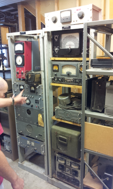
This is a collection of electronics equipment and parts that I purchased last year, which belonged to Bob Sewell. It was an interesting synchronicity that this was all sitting on shelves in a basement in a house literally across the street from me.
In December of 2014, a post was made about the regenerative electric car he invented back in the 1950’s, which was featured in the November 1957 issue of Popular Mechanics. You can see that here: http://emediapress.com/2014/12/27/robert-l-bob-sewell-regenerative-electric-car-inventor
My shop is almost finished and I’ll be able to go through and test some of these devices to see what works and whatever I don’t need will probably be donated to EPD Laboratories, Inc, Eric Dollard’s non-profit organization if there is anything useful to him for his projects.

